I made a video on my annealer, as I just finished a big update to it.
Big things I've learned..
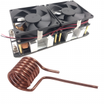
1. Using table salt to wind the main coil is the way to go. Works way better than the ice methods.
2. If I built this without errors from scratch, I'd be in $850 on it. I've got more than that in it due to screw ups and parts replacements. An AMP makes a *lot* of sense.
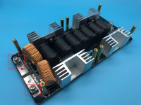
3. You really don't need crazy power. I'm using a 1kW power supply, and this adds a lot of cost if you want to be able to handle that power effectively. 600w is fine.
But it was a fun project, and it works.
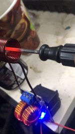
I give you, the Brass Brutalizer 1000.

Big things I've learned..
1. Using table salt to wind the main coil is the way to go. Works way better than the ice methods.
2. If I built this without errors from scratch, I'd be in $850 on it. I've got more than that in it due to screw ups and parts replacements. An AMP makes a *lot* of sense.
3. You really don't need crazy power. I'm using a 1kW power supply, and this adds a lot of cost if you want to be able to handle that power effectively. 600w is fine.
But it was a fun project, and it works.
I give you, the Brass Brutalizer 1000.