• Watch Out for Scammers!

    We've now added a color code for all accounts. Orange accounts are new members, Blue are full members, and Green are Supporters. If you get a message about a sale from an orange account, make sure you pay attention before sending any money!

Help- need A5 clip slot dimensions

FUNCTIONAL

Dirty Civilian
Full Member
Minuteman
  • Feb 19, 2012
    1,870
    1,829
    Eastern, NC
    Could have swore I squirreled away some measurements but for the life of me can't find them. Supposed to do A1 and A5 cuts on my rifle Sunday and coming up short. Only have that one M40 dwg.

    Anyone willing to PM me a set for A5 or either?

    If I recall the A1 was just to the m40 spec so I believe I'm good in that.
     
    If I recall the A1 was just to the m40 spec so I believe I'm good in that.

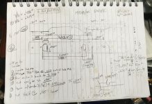
    Best I could find was the info on this link (picture attached)

    "Over the years I’ve searched and I still can’t find a set of drawings for lug slotting a mount. Talking to Dan Ross (D.D. Ross) who designed the mount for the Marines, and Dave Clark (CHPWS), the former Staff Non-Commissioned Officer-in-Charge (SNCOIC) of the Precision Weapons Section at Quantico, they both suggested measuring the mount and cutting it to fit. I took their advice and made the drawing of the mount above. A quick note: I’ve lug slotted two receivers prior to this, so, I am still in the process of fine tuning the process, measurements and drawings."
    ***
    Fwiw, attached is the hand drawing that the author mentioned. Dave Clark did my M40A5, and I think he used the lugs on the BO scope rail to mark-up the receiver for the 'lug-slot.' I didn't ask him about a drawing, but I think the above information is correct. (I have noted slightly different shapes on the 'thumb relief' cuts on original M40A1s, presumably as that has done by hand back then).

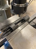
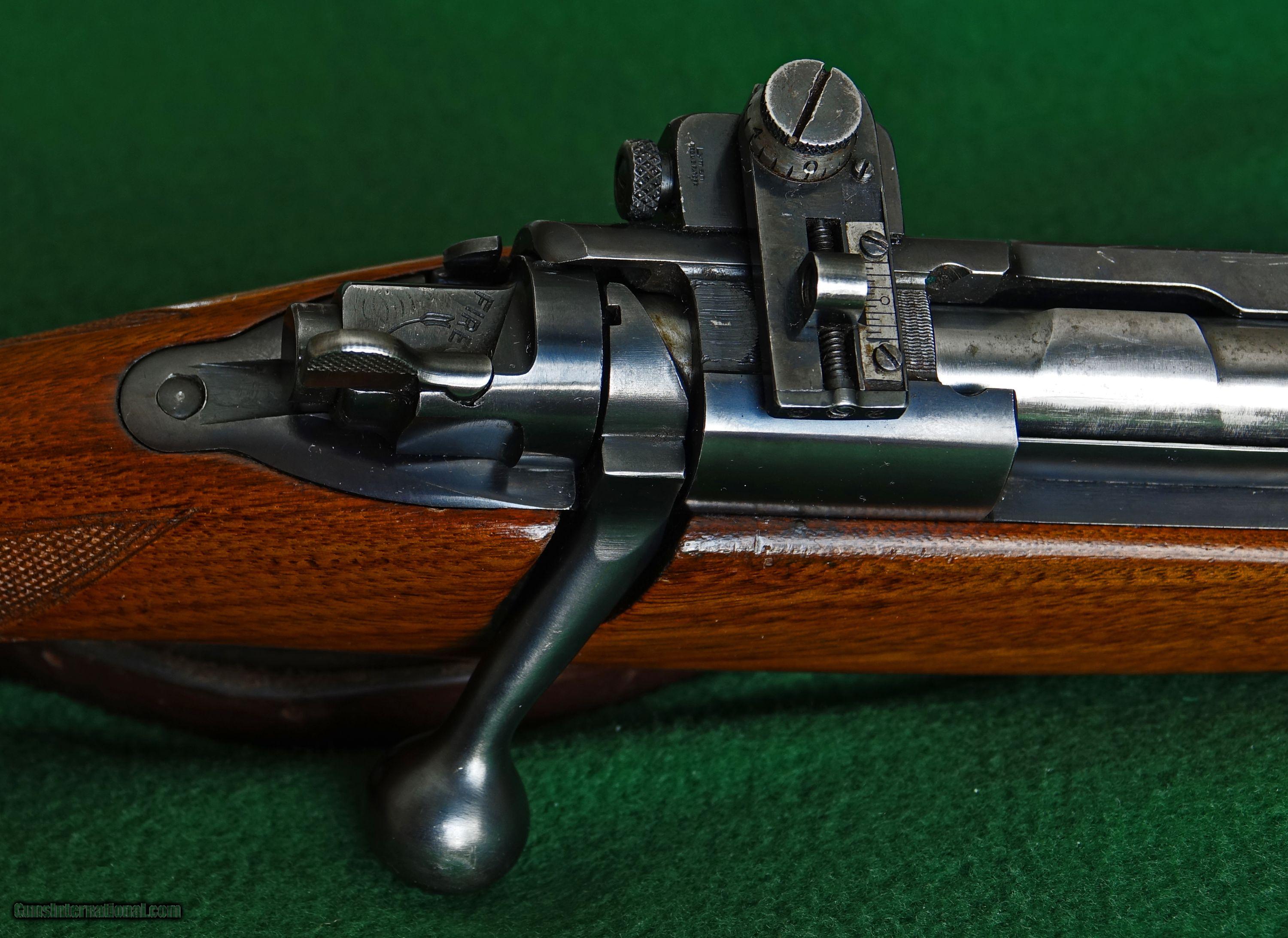
    One nuance, the 1966-1969 M40s were factory "clip slotted" and thus had two small divots or semi-circular cuts on each side- to accommodate the 5-rd stripper clip so they would be held in the receiver's clip slot. (These were used back then to rapidly load 5 rds from the top for the rapid fire section of a rifle match, but obviously superfluous for a scoped rifle). White arrows are what I mean by factory "clip slotting" on the original M40s.

    M40 clip slot_arrows.jpg


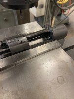
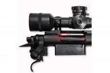
    In a slight contrast, when it came to modifying the C, E, G M700 receivers for the M40A1/A3/A5 variants, my understanding is the USMC just "lug slotted" the receivers - and didn't bother with the two semi-circular "clip" slots as their was no need to do that extra machining - as 5-rd stripper clips would never be used on those sniper rifles. Here's what a retired 2112 did for my replica, and it looks hand-done. It lacks the "clip" cuts as seen above. (Fwiw, years ago at a match at Quantico, I heard one old 2112 joke/confess that he screwed up one time doing the lug slot on an M40A1 in mid-90s, as it done by hand).

    M40A1_lug_slot_top2_v2.jpg


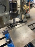
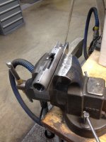
    Lastly, two retired MOS 2112s told me that on M40A1s they cut the rear slot a tiny bit short (maybe 0.001?), and would hand-file the back of the lug on the Unertl scope mount so it would just fit into the slot on the receiver, with no play. (see white arrow where they would hand-file to fit a particular lug slot).
    Yes, it was tedious, but that's what I was told was the SOP back in the 1990s. That's also what they did on my replica as well - its a tight fit.
    M40A1_scope_base_arrow.jpg


    Anyhow, that's all I know. Perhaps others know more, and good luck with your project.
     

    Attachments

    • lug-slot-drawing-USMC-M40A3-build-M40A5.jpg
      lug-slot-drawing-USMC-M40A3-build-M40A5.jpg
      358.3 KB · Views: 80
    Last edited:
    @Random Guy Thank you very much. I had this saved and I cannot find where I did. Either way it doesnt matter now because this will do.

    I will say based on what I've seen from Raven on other forums 7/16 is not the ball endmill to use on the A3/A5 thumb cut. I used this to do my 223 A6 barreled action and the thumb cut did not look correct compared to my A5 Raven did. If I recall the 3/4" ball end was correct for the a3/5/6 and the 7/16 was correct for the A1.

    Again I appreciate it, saved me a lot of headache backwards measuring from my other 2 lug slot receivers.
     
    Actually the A3/A5 is cut with the action laying on it's side with the base holes against the mill vise jaw and you plunge with 3/4" diameter carbide endmill. This is just for the thumb notch. Man wonder how many hits I would get on Youtube showing how to Clipslot a M40A3/5? lol
     
    Last edited:
    @Raven 6 would make at least a few dozen just from me 🤣

    They are done... not going to say we'll though. The A3/5 cut I believe is passable with the exception of the thumb cut. Had no idea it was done on its side. Used a ball nose and went about mid gas port and deep enough to match the base curve. On the bright side I don't think this would be hard to correct. Rail fit damn near as tight as Mark did for me years ago.

    The A1 is another story unfortunately. Can't tell if the base was fucked (from our favorite remanufactured parts supplier) or what. Dimensions exceeded what prints you shared and I could find and I had to modify the base before things got too crazy with the inlet. Not to mention the scope holes wouldn't like up and I ended up have to trim quite a bit off the bases rear lug. Thankfully I only do this crap for myself.
     
    Let's keep this one alive. If anyone has a specific question on clip slotting I will do my best to answer, I don't know everything but I'll share what I do know.
     
    • Like
    Reactions: Average guy
    Here is when my A3 was built and can confirm this was lug slotted vs clip slotted.
     

    Attachments

    • IMG_3607.JPG
      IMG_3607.JPG
      386.9 KB · Views: 81
    • Like
    Reactions: Phil McGrath
    Let's keep this one alive. If anyone has a specific question on clip slotting I will do my best to answer, I don't know everything but I'll share what I do know.
    I'd really like to do the thumb relief cut for a M40. Does anyone have the specifics on size of the mill used/ and an exact reference measurement for the center of the bit? Thanks.
     
    I will say the M40 drawing two posts above were how Remington did them on early, early, early in the M40 line up and the arrow on the thumb cut that is missing is also .33 R but location is anyone's guess. Once the rifles started being build by Quantico that thumb grove was no longer done due to the complexity I would say. This started with your 221***, 224***, and 332*** actions. I will tell you how I do them, you can decide how you want to do them. I have the action in the Badger action block with the area to get the thumb slot is up. The centerline of the thumb grove is .236" down from the top of the action and 2.236" from the front of the ejection port which in the drawing above is your "X" zero. Use a 11/16" diameter carbide endmill. DO NOT TRY TO CUT ALL AT ONE TIME. Once you have complete thumb notch cut you will need to cut toward the top of the action to finish the cut, there is approximately .100" flat leading down to the start of the radius. This is how I've done them, cut at your own risk.
     
    One last note on the M40 drawing above. If you want that thump notch with the "S" notch see my dimensions above but instead of the .236" "Y" Dimension use .200" and then use a dremal tool to hand sand the point to create the "S" version. It's not hard but you should take your time. Good Luck.
     
    • Like
    Reactions: Phil McGrath
    @Raven 6 would make at least a few dozen just from me 🤣

    They are done... not going to say we'll though. The A3/5 cut I believe is passable with the exception of the thumb cut. Had no idea it was done on its side. Used a ball nose and went about mid gas port and deep enough to match the base curve. On the bright side I don't think this would be hard to correct. Rail fit damn near as tight as Mark did for me years ago.

    The A1 is another story unfortunately. Can't tell if the base was fucked (from our favorite remanufactured parts supplier) or what. Dimensions exceeded what prints you shared and I could find and I had to modify the base before things got too crazy with the inlet. Not to mention the scope holes wouldn't like up and I ended up have to trim quite a bit off the bases rear lug. Thankfully I only do this crap for myself.
    Anyone who uses one of his base set is going to run into the same problem. His rear lug is left oversize intentionally with the though of filling it to match the clip slot on your action. But if you have Virgin action you can cut the action to fit the base which is much easier. The very first thing to check his base with a straight edge, more than likely it's not straight. If at all possible try to straighten it with a hand press.
     
    Clip-slotting the Winchester 70 and Remington 40X allowed Camp Perry bolt-gunners the ability to load like the Springfield while military shooters were using the M1.

    WINCHESTER-MODEL-70-PRE-WAR-STANDARD-RIFLE-7X57-CALIBER-1937_100990487_5287_0C4B8125C8AFE8F5.jpg
    model70.jpeg
    maxresdefault.jpg


    Fred on the Maryland Rifle Team impressed the heck out of me when I watched him shoot the rapids at a Quantico Regional Match. All shooters start in the standing position and when targets rise up over the berm everyone assumes the sitting position and fires (two rounds and a magazine change of eight if shooting an auto-loader, and five-and-five with a stripper clip change if a bolt gun -- all in 60 seconds at 200 yards. You get ten extra seconds when going from standing to prone at 300 yards). Watching a guy shoot, follow through, bolt the gun, and repeat with five seconds to spare was like watching angels dancing.

    The Marines finally figured out butting the mounts against the stripper clip slot and the forward receiver round to keep mount screws from shearing.
     
    One last note on the M40 drawing above. If you want that thump notch with the "S" notch see my dimensions above but instead of the .236" "Y" Dimension use .200" and then use a dremal tool to hand sand the point to create the "S" version. It's not hard but you should take your time. Good Luck.
    Thanks Raven. This clears everything up for me...
     
    I don't know if this has been asked...when is it required to cut the flat on the back side of the receiver? Is this a M40A3/ A5 cut only? or was it also done on the M40 and M40A1? Hope this make sense, let me know and I can clarify if needed...Thanks.

    I found the answer to my question and apologize for hijacking this "M40A5 clip slot dimensions" thread to a "M40/ M40A1 clip slot dimensions" thread.
    Thanks for all the help.
     
    Last edited:
    One last note on the M40 drawing above. If you want that thump notch with the "S" notch see my dimensions above but instead of the .236" "Y" Dimension use .200" and then use a dremal tool to hand sand the point to create the "S" version. It's not hard but you should take your time. Good Luck.
    I did a rough drawing of your dimensions. Are these correct?
    Thanks again.
     

    Attachments

    • 6 digit s cut2.jpg
      6 digit s cut2.jpg
      291.1 KB · Views: 33