Since I am very happy wit the Jewell trigger in my B14R, I felt confident enough to grind away the rivet heads and open the stock Bergara trigger to have a look inside.
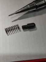
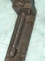
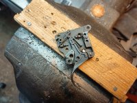
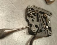
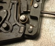
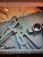
The first picture can be used as a reference, second picture I assembled the top trigger spring the wrong way! Anyway, this is what we get after removing the (riveted) cover plate:

So apart from polishing and maybe different springs, not much to be done. But it also shows why Bergara can confidently say it's safe to remove the adjustment screw for the pull weight. It still acts on the trigger and there are two springs working against the trigger anyways.
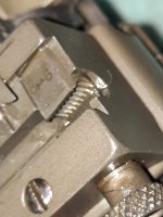
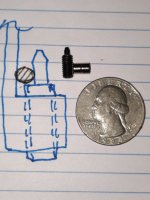
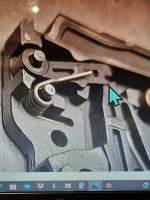
The second thing - which was a bit surprisin to me - is that there are two holes pre-drilled in the trigger housing!

^number one could be threaded and then used to adjust the sear engagement!! I am rather surprised to see that it's there but not used. Maybe they went for the safe option somewhere during development to have a "lawyer freindly" trigger? I don't know. But putting an adjustment screw there would greatly increase the adjustability of the factory trigger.
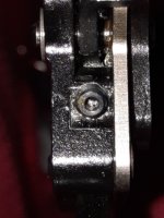
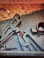
The second hole:

This would make a nice trigger stop.
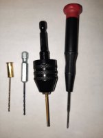
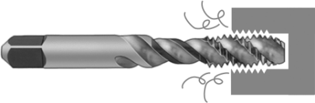
If i feel the urge I may try to find a way to put this back together, however drilling & tapping these holes does NOT require the trigger to be disassembled like this! And as always; if you do any work on your trigger make sure the gun is still safe afterwards!!
Though this could be interesting enough for some folks who do not want to spend the money on a new trigger right away...") I know I would have tried this first, had I looked at it closer before ordering a Jewell
I know I would have tried this first, had I looked at it closer before ordering a Jewell
Cheers!
The first picture can be used as a reference, second picture I assembled the top trigger spring the wrong way! Anyway, this is what we get after removing the (riveted) cover plate:
So apart from polishing and maybe different springs, not much to be done. But it also shows why Bergara can confidently say it's safe to remove the adjustment screw for the pull weight. It still acts on the trigger and there are two springs working against the trigger anyways.
The second thing - which was a bit surprisin to me - is that there are two holes pre-drilled in the trigger housing!
^number one could be threaded and then used to adjust the sear engagement!! I am rather surprised to see that it's there but not used. Maybe they went for the safe option somewhere during development to have a "lawyer freindly" trigger? I don't know. But putting an adjustment screw there would greatly increase the adjustability of the factory trigger.
The second hole:
This would make a nice trigger stop.
If i feel the urge I may try to find a way to put this back together, however drilling & tapping these holes does NOT require the trigger to be disassembled like this! And as always; if you do any work on your trigger make sure the gun is still safe afterwards!!
Though this could be interesting enough for some folks who do not want to spend the money on a new trigger right away...
I know I would have tried this first, had I looked at it closer before ordering a Jewell Cheers!