• Watch Out for Scammers!

    We've now added a color code for all accounts. Orange accounts are new members, Blue are full members, and Green are Supporters. If you get a message about a sale from an orange account, make sure you pay attention before sending any money!

Gunsmithing Action truing fixture idea

chipsfan

Sergeant
Full Member
Minuteman
Jun 20, 2009
333
1
48
Northeast USA
Hi,

I've been using one of those big aluminum ones from Viper's Benchrest.

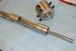
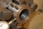
I am thinking about making a shorter one, with the screws offset to work in between the jaws of my four jaw chucks. I've determine it needs to be at least 4.5" long so I can grab the action on the front and back of the magazine and ejection port cut outs. I have a piece of 304 Stainless steel tubing, it has 1/4" thick walls. inside diameter is 1.7" Do you think this would work?

Thanks,
Bill
 
Last edited:
That will work fine and it can actualy be much shorter than that , all you need to grab in the front action ring.
Here are Some pics from "wnroscoe" web site of his trueing jig. I use to use a bog jig like Greg Tannel sold and found this musch smaller one to be much more rigid and easier to setup.

Roscoe has a lot of pics on his web site that will help guide a fella through the process
Louisiana Precision Rifles, LLC - Precision Firearms - A list of custom reamers we use to chamber barrel blanks
 

Attachments

  • receiver-truing-004.jpg
    receiver-truing-004.jpg
    62.2 KB · Views: 162
  • receiver-truing-006.jpg
    receiver-truing-006.jpg
    61.4 KB · Views: 95
That will work fine and it can actualy be much shorter than that , all you need to grab in the front action ring.
Here are Some pics from "wnroscoe" web site of his trueing jig. I use to use a bog jig like Greg Tannel sold and found this musch smaller one to be much more rigid and easier to setup.
J
Roscoe has a lot of pics on his web site that will help guide a fella through the process
Louisiana Precision Rifles, LLC - Precision Firearms - A list of custom reamers we use to chamber barrel blanks

I use to use the heavy long truing jig for years. Now I also use the same set up. It is tight up against the chuck, and way smaller in diameter, so the lathe doesnt need to be real big and rigid. You will have to make your own because I've not seen it for sale anywhere, buts fairly easy to make. I also got the idea from William. In my opinion, this works better than the big heavy jig. Best of luck.
 
Thanks guys- those screws are grabbing the front of the receiver? Forward of the ejection port cut?

Are those aluminum shims in there?
 
What is the point of this jig? To me it looks like you can do the same thing with alum shims and the 4 jaw... maybe I'm missing something

Sent from my SCH-I605 using Tapatalk
 
What is the point of this jig? To me it looks like you can do the same thing with alum shims and the 4 jaw... maybe I'm missing something

Sent from my SCH-I605 using Tapatalk

These are used to gimbal the receiver until the bore centerline is concentric with the spindle axis.
 
Last edited:
That can be done in a 4 jaw with an indicator

Sent from my SCH-I605 using Tapatalk
 
Maybe you could explain this gimbal term since I'm not getting it.

Sent from my SCH-I605 using Tapatalk
 
After looking at his set-up on the site. Yes you can get that indicating shaft straight and concentric using just a 4 jaw

Sent from my SCH-I605 using Tapatalk
 
After looking at his set-up on the site. Yes you can get that indicating shaft straight and concentric using just a 4 jaw

Sent from my SCH-I605 using Tapatalk

And if there is angular misalignment between the bore and OD of the receiver?
 
All you care about is that the bore of the receiver is running true and straight front to back? And you are only cutting the front inch or so of the receiver?
Or do you want the OD true to the bore?
Sent from my SCH-I605 using Tapatalk
 
Last edited:
All you care about is that the bore of the receiver is running true and straight front to back? And you are only cutting the front inch or so of the receiver?

Sent from my SCH-I605 using Tapatalk


Re-cutting the threads parallel and concentric to that axis. Facing the lug abutments and receiver face perpendicular to that axis.
 
The alum shims will match the irregularities of the OD and as long as you indicate that shaft as true as you want a 4 jaw can manipulate a piece just about anyway you could think of

Sent from my SCH-I605 using Tapatalk
 
The alum shims will match the irregularities of the OD and as long as you indicate that shaft as true as you want a 4 jaw can manipulate a piece just about anyway you could think of

Sent from my SCH-I605 using Tapatalk
a 4 jaw will only get the action running strait in line with the bolt race way at one point , you need to be able to adjust the back of the action so the can "tilt" it front to back and get the bolt race way strait. The action indicationg rod stick out in front of the action several inches , you need to have it running strait with no wobble at the action nose and at the end of the rod , their are several videos here explaining this. the action is held in this jig by a sleeve so that the screws don't mar the finish and it also allows a better grip on the action. Whenb gripping it by the front ring only it eliminated the possibility of putting stress in the action. You can use only a 4 jaw , 3 jaw true set or precision 6 jaw if you want but you will need an adapter that allows you to "tilt" the chuck.
Nathan Dagley make such a fixture and can be found here in this forum , I recommend watching the videos and it will help explain the "axis" we are referring to

link
http://www.snipershide.com/shooting...y-awesome-barreling-action-truing-system.html
 
The alum shims will match the irregularities of the OD and as long as you indicate that shaft as true as you want a 4 jaw can manipulate a piece just about anyway you could think of

Sent from my SCH-I605 using Tapatalk

The OD isn't necessarily irregular. A 3, 4 or 6 jaw chuck or collet has no problem gripping it. You'd take a week trying to shim the receiver OD at an angle that would bring the bore into alignment to a couple tenths over 5 inches though.
 
I understand the axis you are talking about, the one that is represented by the indicating rod totally on board.

Sent from my SCH-I605 using Tapatalk
 
The OD isn't necessarily irregular. A 3, 4 or 6 jaw chuck or collet has no problem gripping it. You'd take a week trying to shim the receiver OD at an angle that would bring the bore into alignment to a couple tenths over 5 inches though.

Even with a center drill in the end of the rod using a dead center to get it close, remove the tail stock, dead blow the last 2 thou and start making chips. Sorry I just learned in shops not to trust set screws and jigs when working tight tolerances... If this works for you guys more power too ya.

Sent from my SCH-I605 using Tapatalk
 
Help me understand this. If the front of the action is in your 4 jaw, just what are you bashing on to bring the length of the bolt raceway into alignment with the lathe spindle? Your precision ground alignment rod? And you can achieve alignment the full length of the bushed alignment rod by doing this in a 4 jaw. I would like to see some pictures of this process.
 
I would make adjustments by using a brass or aluminum rod to the back end of the action between the spaces of the jaws. Best case scenario would be hold the rear in the 4 jaw and use a steady rest for the front. I just see a mini 4 jaw in a 4 jaw when I see that jig in the original picture.

Sent from my SCH-I605 using Tapatalk
 
Help me understand this. If the front of the action is in your 4 jaw, just what are you bashing on to bring the length of the bolt raceway into alignment with the lathe spindle? Your precision ground alignment rod? And you can achieve alignment the full length of the bushed alignment rod by doing this in a 4 jaw. I would like to see some pictures of this process.

You could even hold closer to the center of the action by using a block of alum to bridge the gap of the ejection port, nobody said the front of the action has to be flush with the jaws.

Sent from my SCH-I605 using Tapatalk
 
I am trying to understand, as well as a machinist I am trying to offer my perspective if I had to do the job.

Sent from my SCH-I605 using Tapatalk
 
I would make adjustments by using a brass or aluminum rod to the back end of the action between the spaces of the jaws. Best case scenario would be hold the rear in the 4 jaw and use a steady rest for the front. I just see a mini 4 jaw in a 4 jaw when I see that jig in the original picture.

Sent from my SCH-I605 using Tapatalk

What you are obviously not seeing is the jig has TWO sets of 4 jaws that independently adjust allowing the receiver to gimbal.
 
Even with a center drill in the end of the rod using a dead center to get it close, remove the tail stock, dead blow the last 2 thou and start making chips. Sorry I just learned in shops not to trust set screws and jigs when working tight tolerances... If this works for you guys more power too ya.

Sent from my SCH-I605 using Tapatalk
The cuts made to a reciever are very light , generally on .001" at a time facing the integral lugs and reciever face maybe .003" at a time to clean up the threads.
The idea of chucking up on the rear of the action and run the front in a steady rest will work but it take longer to dial the action in. The fixture in the pic is very solid and would take something very bad to happen in order to knock it out of alignment.
Trying to deadblow a reciever into alignment of .0002" that was only chucked on the front ring would be impossible in my oppinion not to mention ruining the finish
 
The O.P was talking about doing this work with out a jig or making his own, that tells me he is probably doing a one off for himself. I just was throwing ideas out there to save him hours on making a fixture. There are a hundred different ways to do it, I'll go back in my hole.

Sent from my SCH-I605 using Tapatalk
 
For the couple hrs it would take to make a jig would pay off with an easier tool to true the action and you have it in case you ever wanted to do it again. I assure you that time and head ache trying to shim and or "drift" an action into axial alignment with a standard 4 jaw chuck would be FAR outweighed with making a tool.
I have use a steady rest to bluepint a Rem action and it worked but took at least twice as long to dial in accurately than with a jig and it was a pain in the ass trying to work around it.
I'm working on building a tool/chuck adapter like Nathen Dagley sells to mount a 6 jaw chuck to. In the past I have used a couple different jigs to hold short barrels and actions and I think that if building or buying a unit like Nate's is not available then the small fixture that Roscoe uses is the way to go
 
To each his own I guess, it's just something I had a knack for
dialing in odd parts in a 4 jaw I also spent every day doing it, where as you may do it once a month in this situation

Sent from my SCH-I605 using Tapatalk
 
Chips fwiw I switched the the shorter style that JJones has pictured. It is much easier to dial in the action without fleixng or binding it in the fixture. It also holds the workpiece closer to the chuck which helps eliminate chatter and deflection.YMMV
 
If you can get your receiver running to less than .00005" TIR by tapping, bashing or prying my hats off to you, I wouldn't even try it. The screws make it 1000% easier and faster to do so. For those asking, there's an aluminum sleeve that slips over the receiver and then the total package slips into the fixture for alignment. The sleeve is tight once over the receiver. There's no magical clearance required between fixture and sleeve but, enough space is required for the receiver to gimble around and be adjusted to run "True" The screws never touch the receiver or mark it up.
 
I copied Williams also, heres the sleeve I made


And the jig all together with an action in it


Are you guys boring solid stock for the body or using thick walled tube? Whats the ID of the steel tube? and space between the sleeve and the body?

I was going to use some scrap I had lying around. Now I am thinking I might as well pony up and buy some materials and do it right. I am a cheap SOB.
 
I bored mine from solid stock I had. The sleeve started out 1/4" but I made that smaller then slit it. Like William said the sleeve fits just snug on the action and theres a little room between the fixture and sleeve to manipulate the action.
 
Scotty, the receiver bore has to be on center and straight.
That's why there are 2 adjustment screws on each side.
The receiver OD probably is neither concentric nor parallel to the bore from the factory.
 
I'm guessing he's using an indicator with 0.1000" precision...

I made mine so the sleeve stays with the fixture. Just makes it easier if you want to do multiple actions while leaving fixture dialed in. Obviously the sleeve still has full range movement.

a3yruvu9.jpg


Galaxy S3 on tapatalk
 
While you're making fixtures, I like this far better than using the old style action jig for bolts. It could have been a little beefier, but you're making even lighter cuts on the bolt than you do on the action so I just used what I had at the time. If youre wondering, this one just has a steel sleeve that is .700id x 1" od and cut in half.

dybe5uha.jpg


Galaxy S3 on tapatalk
 
Last edited:
I'm guessing he's using an indicator with 0.1000" precision...

I made mine so the sleeve stays with the fixture. Just makes it easier if you want to do multiple actions while leaving fixture dialed in. Obviously the sleeve still has full range movement.

a3yruvu9.jpg


Galaxy S3 on tapatalk


I like it.
 
While you're making fixtures, I like this far better than using the old style action jig for bolts. It could have been a little beefier, but you're making even lighter cuts on the bolt than you do on the action so I just used what I had at the time. If youre wondering, this one just has a steel sleeve that is .700id x 1" od and cut in half.

dybe5uha.jpg


Galaxy S3 on tapatalk

How do you indicate that in?
 
The two piece inner sleeve is say 1" outside diameter, the inside diameter of the outer piece is like 1.1" (cant remember exact dimensions off hand). Then it just gimbals the same as the action fixture pretty much. Have to make sure the split in the inner sleeve lines up just right with the jack screws when you insert it.
 
While you're making fixtures, I like this far better than using the old style action jig for bolts. It could have been a little beefier, but you're making even lighter cuts on the bolt than you do on the action so I just used what I had at the time. If youre wondering, this one just has a steel sleeve that is .700id x 1" od and cut in half.

dybe5uha.jpg


Galaxy S3 on tapatalk

Thank you for posting that pic. I think I'll be making one of these as well
 
The two piece inner sleeve is say 1" outside diameter, the inside diameter of the outer piece is like 1.1" (cant remember exact dimensions off hand). Then it just gimbals the same as the action fixture pretty much. Have to make sure the split in the inner sleeve lines up just right with the jack screws when you insert it.

What two locations are using to indicate on?
 
What two locations are using to indicate on?
I'm guessing on the short area between the jig and the behind the bold lugs.
I though about doing something like this but my idea would look like this jig in backwards and use a spud screwed into the back of the bolt for the rear screws to act on*and the front screws would contact just in front of the bolt handel leaving nearly a full bolt length to indicate off off. My concern was that having the fixture and the bolt sticking W A Y off the chuck unsupported would cause issues but I guess if you used sharp tooling and lower speeds it would work

I've run bolts in the La Bounty fixture and the bolt is pretty far out from the chuck. It works well bc the cut is so light.
 
I'm guessing on the short area between the jig and the behind the bold lugs.
I though about doing something like this but my idea would look like this jig in backwards and use a spud screwed into the back of the bolt for the rear screws to act on*and the front screws would contact just in front of the bolt handel leaving nearly a full bolt length to indicate off off. My concern was that having the fixture and the bolt sticking W A Y off the chuck unsupported would cause issues but I guess if you used sharp tooling and lower speeds it would work

The point I'm trying to make is some setups are reliable and some aren't. Don't fall into the trap that what works for one process automatically works for another. How reliable/accurate are those two points. First they are not very far apart compared to the length of the bolt. That introduces error that's multiplied over the length of the bolt. Then Remington bolts are made from three pieces. The handle, the body (tubular) and the head which is soldered and pinned to the body. I have never seen the heads attached with any kind of precision. It is never in perfect alignment with the body. Also I have seen bodies that were banana shaped.

To test this turn a 60 degree center on a piece of round stock. You should have this already made already. Put it in a 4 jaw chuck or an adjustable three jaw chuck. Just for giggles indicate that in if done in a 3 jaw and then transferred to a 4 jaw. Put the rear of the bolt on this center and lightly put the center in the tailstock in the firing pin hole. Run an indicator back and forth along the bolt body and see what you get. Then adjust the chuck trying to achieve zero run out front to rear in 4 locations 90 degrees apart on the body. Don't worry about the run out radially. That's not important in this process. Go between the lugs all the way to the nose. Somewhere in the process you'll say this is as good as I can get it. That's when you take a light cut on the rear of the lugs. Then check radially in several places along the body as part of the learning process.

An alternative setup is to screw a stub in the rear of of the bolt. Put it in the lathe clamping on the bolt body, take a clean up cut on the stub(maybe 3/8" long), swap ends holding the stub in the chuck and go through process of aligning the body.
 
Mr. Tooley you make a great case to just buy a new bolt from PTG , which is what I have done with my last 3 builds because I reamed the bolt race way.
I think for the money they are very hard to beat
 
Mr. Tooley you make a great case to just buy a new bolt from PTG , which is what I have done with my last 3 builds because I reamed the bolt race way.
I think for the money they are very hard to beat

My name is Dave. Mr. Tooley passed away 8 years ago today. Everything is a compromise. Perfection costs money and you reach a point of diminishing returns very quickly.
 
I have found most of the remington bolts i have worked on were egged or oblong shaped. I try to indicate the opposing jaws to the same zero while the bolt is held in a labounty fixture. My receiver jig just holds the front receiver ring and uses a brass bushing that allows .020 clearance between the bushing and jig. It makes dialing in the receiver a lot faster! Does anyone have opinions or theories on the labounty fixture and its accuracy for bolt work? I use it because its so much easier and quiker than the stub and steady method.

Chuck
 
The point I'm trying to make is some setups are reliable and some aren't. Don't fall into the trap that what works for one process automatically works for another. How reliable/accurate are those two points. First they are not very far apart compared to the length of the bolt. That introduces error that's multiplied over the length of the bolt. Then Remington bolts are made from three pieces. The handle, the body (tubular) and the head which is soldered and pinned to the body. I have never seen the heads attached with any kind of precision. It is never in perfect alignment with the body. Also I have seen bodies that were banana shaped.

To test this turn a 60 degree center on a piece of round stock. You should have this already made already. Put it in a 4 jaw chuck or an adjustable three jaw chuck. Just for giggles indicate that in if done in a 3 jaw and then transferred to a 4 jaw. Put the rear of the bolt on this center and lightly put the center in the tailstock in the firing pin hole. Run an indicator back and forth along the bolt body and see what you get. Then adjust the chuck trying to achieve zero run out front to rear in 4 locations 90 degrees apart on the body. Don't worry about the run out radially. That's not important in this process. Go between the lugs all the way to the nose. Somewhere in the process you'll say this is as good as I can get it. That's when you take a light cut on the rear of the lugs. Then check radially in several places along the body as part of the learning process.

An alternative setup is to screw a stub in the rear of of the bolt. Put it in the lathe clamping on the bolt body, take a clean up cut on the stub(maybe 3/8" long), swap ends holding the stub in the chuck and go through process of aligning the body.

+1

bow28.gif
 
I have found most of the remington bolts i have worked on were egged or oblong shaped. I try to indicate the opposing jaws to the same zero while the bolt is held in a labounty fixture. My receiver jig just holds the front receiver ring and uses a brass bushing that allows .020 clearance between the bushing and jig. It makes dialing in the receiver a lot faster! Does anyone have opinions or theories on the labounty fixture and its accuracy for bolt work? I use it because its so much easier and quiker than the stub and steady method.

Chuck

The LaBounty jig is convenient not precise. You're trying to achieve perpendicularity between the lugs and the bolt body. You can't do it with that fixture.