

Hey guys. Is there a good source of cad drawings for r700 or custom actions (besides the US Patent Office)?
Gunsmithing CAD Drawings
- Thread starter idahoshooter
- Start date
You are using an out of date browser. It may not display this or other websites correctly.
You should upgrade or use an alternative browser.
You should upgrade or use an alternative browser.
Re: CAD Drawings
Hey mate,
Dont like your chances somehow. Im a mechanical draftsman, drawings dont come cheap so i doubt manufactures will be willing to give them out, and the fact someone else could make an working action off it.
Send me over a action and i'll happily turn it into a nice 3d model for you, might have to keep the action afterwards though.lol.
Would like to see some cad models of rifle actions though. Maybe Surgeon Rifles can give me a job, that would be nice..haha
Pete
Re: CAD Drawings
From an OEM? Not a chance.
I tried contacting a reputable manufacturer asking the same question when I was building a custom stock and got told to f**k off.
Quite understandable really...!
Rich
From an OEM? Not a chance.
I tried contacting a reputable manufacturer asking the same question when I was building a custom stock and got told to f**k off.
Quite understandable really...!
Rich
Re: CAD Drawings
I got some stuff that I generated on my own.
I got some stuff that I generated on my own.
Re: CAD Drawings
If you just want a model to work off of, a laser will generate a 3d scan of a part like an action in about 1.5 hrs. A good CMM and operator could do it also in a day. Then build the solid off the data.It will only tell you exactly whats there. GD&T ,along with material selection and processing, will have to be "dreamed up" on your own if you actualy want to make it.... correctly.
C.Dixon,I like watchin your stuff. Pull a vacuum on your bedding compound in the container after its mixed,no wait for air to escape mixture and gets all of it out of the bedding compound.
Re: CAD Drawings
Thanks,
I don't mix in a container.
Order of operations is everything in my book A guy can pull air only to introduce it again when applying it to the stock.
I've solved that problem. Waiting is part of the process. There's more but I like to keep some parts of this proprietary.
C
Thanks,
I don't mix in a container.
Order of operations is everything in my book A guy can pull air only to introduce it again when applying it to the stock.
I've solved that problem. Waiting is part of the process. There's more but I like to keep some parts of this proprietary.
C
Re: CAD Drawings
I've been working on it.
this is an LA Clone. I did not have time to double check, this is only a first verion.
You will need Solid Works to open.
http://rapidshare.com/files/431298950/Rem_M700_LA.zip
I've been working on it.
this is an LA Clone. I did not have time to double check, this is only a first verion.
You will need Solid Works to open.
http://rapidshare.com/files/431298950/Rem_M700_LA.zip
Re: CAD Drawings
<div class="ubbcode-block"><div class="ubbcode-header">Originally Posted By: Jan</div><div class="ubbcode-body">I've been working on it.
this is an LA Clone. I did not have time to double check, this is only a first verion.
You will need Solid Works to open.
http://rapidshare.com/files/431298950/Rem_M700_LA.zip </div></div>
Someone be a guinea pig and open this zip file ......please.
Re: CAD Drawings
<div class="ubbcode-block"><div class="ubbcode-header">Originally Posted By: C. Dixon</div><div class="ubbcode-body">Thanks,
I don't mix in a container.
Order of operations is everything in my book A guy can pull air only to introduce it again when applying it to the stock.
I've solved that problem. Waiting is part of the process. There's more but I like to keep some parts of this proprietary.
C </div></div>
is it a proprietary cetrifuge. That would get the air moving....
I feel like Im geting to old to wait "for the paint to dry".
Just messing with ya .
Re: CAD Drawings
As far as drawings go, I came across this with a thorough Google search a few days ago.
But during the search for the above drawing, I came across the list below. Access to the list is open, but access to the drawings referenced therein requires a subscription to a forum that I'm not willing to subscribe to at this point. As a result, I can make to assurance as to the accuracy or content to any information that may be contained there.
List of Drawings
Re: CAD Drawings
I hate websites that require you to pay prior to seeing anything.........
I hate websites that require you to pay prior to seeing anything.........
Re: CAD Drawings
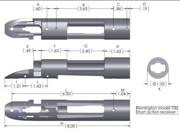
Tell you right off the tang is wrong in that drawing. The tang requires some creativity to replicate. I've been able to do it but it required some software manipulation to get it right.
2nd the "artist" that conjured up the model doesn't use a reference (datum) for the dimensioning. I've never seen an action print dimensioned starting at the tang. (especially for trigger pin locations. Those would typically be called out from the lug surfaces of the receiver since that's where the bolt qualifies from) Be careful if using this cause your liable to get a tolerance stack that's going to to bite your butt later.
The scope hole locations are also a recipe for disaster and an excellent example of what tolerance stacking can do.
For instance:
In the bottom of most prints you'll find a tolerance block. It'll say something like this:
.01 +/- .005"
.001 +/- .001"
.0005 +/- .0001"
OR it may have this included too:
.01 +0.0/-.001"
So on. . .
What it means is any dimension on a print with that goes two decimals to the right has a tolerance of +/- .005" in actual true position on the part. the others follow suit and go on down the line.
Here's the problem as related to the scope mounts. EACH one of those dimensions would potentially have the +/- tolerance. So, lets say your work is "off" by .002" and your first hole is out of location. What happens to the next? What if your mistaken again or a drill wanders a little on the next hole? Then the next hole and the next hole.
Get the picture?
Depending on the infinite number of ways to screw with this you could end up at the last hole and find that it's out of location by enough to make fitting a scope base bought at a store impossible.
What the "artist" did is called incremental dimensioning because it's quicker to do when drafting. What (IMHO) should have been done here is the use of absolute positioning/dimensioning. Qualify everything from one clearly defined feature (face of the action for instance) Your much less likely to screw it up this way.
That's just the base holes. Look closely at the guard screw locations. What's missing? There's nothing positioning them in relation to the magazine mortise. Going to make fitting a floor metal kinda tough isn't it?
Just sayin. . .
Good luck with your project. Spend your time working on the primary extraction cam. That's the fun part!
C
Re: CAD Drawings
<div class="ubbcode-block"><div class="ubbcode-header">Originally Posted By: C. Dixon</div><div class="ubbcode-body">Tell you right off the tang is wrong in that drawing. The tang requires some creativity to replicate. I've been able to do it but it required some software manipulation to get it right.
2nd the "artist" that conjured up the model doesn't use a reference (datum) for the dimensioning. I've never seen an action print dimensioned starting at the tang. (especially for trigger pin locations. Those would typically be called out from the lug surfaces of the receiver since that's where the bolt qualifies from) Be careful if using this cause your liable to get a tolerance stack that's going to to bite your butt later.
The scope hole locations are also a recipe for disaster and an excellent example of what tolerance stacking can do.
For instance:
In the bottom of most prints you'll find a tolerance block. It'll say something like this:
.01 +/- .005"
.001 +/- .001"
.0005 +/- .0001"
OR it may have this included too:
.01 +0.0/-.001"
So on. . .
What it means is any dimension on a print with that goes two decimals to the right has a tolerance of +/- .005" in actual true position on the part. the others follow suit and go on down the line.
Here's the problem as related to the scope mounts. EACH one of those dimensions would potentially have the +/- tolerance. So, lets say your work is "off" by .002" and your first hole is out of location. What happens to the next? What if your mistaken again or a drill wanders a little on the next hole? Then the next hole and the next hole.
Get the picture?
Depending on the infinite number of ways to screw with this you could end up at the last hole and find that it's out of location by enough to make fitting a scope base bought at a store impossible.
What the "artist" did is called incremental dimensioning because it's quicker to do when drafting. What (IMHO) should have been done here is the use of absolute positioning/dimensioning. Qualify everything from one clearly defined feature (face of the action for instance) Your much less likely to screw it up this way.
That's just the base holes. Look closely at the guard screw locations. What's missing? There's nothing positioning them in relation to the magazine mortise. Going to make fitting a floor metal kinda tough isn't it?
Just sayin. . .
Good luck with your project. Spend your time working on the primary extraction cam. That's the fun part!
C
</div></div>
Couldnt be more right. There are draftman and then there are tracers, this drawing is more of an artist impression.lol.
Pete
Re: CAD Drawings
<div class="ubbcode-block"><div class="ubbcode-header">Originally Posted By: subgunr</div><div class="ubbcode-body"><div class="ubbcode-block"><div class="ubbcode-header">Originally Posted By: Jan</div><div class="ubbcode-body">I've been working on it.
this is an LA Clone. I did not have time to double check, this is only a first verion.
You will need Solid Works to open.
http://rapidshare.com/files/431298950/Rem_M700_LA.zip </div></div>
Someone be a guinea pig and open this zip file ......please. </div></div>
There is no file there. If you can find the file, I will open it.
Re: CAD Drawings
There is no radius given for "F", because they belt sand it!
When I made bases for my Bro I used "H" as the reference and we bedded the back.
The inspector and myself agreed on the front, but we never got the same on the back.
It's a blend, so that's understandable.
Never checked the tangs on his, but would have to agree with that.
Rarebreed is right, there is no file there.
If you want to know how to get dims for something old school I can help.
Not simple shit, but somthing like a trigger group with minimal clearances.
Hell, maybe we can work together on this!
I know how to make a solid, physical model of what's needed, but no way to convert all to a computer model, which is what I need to machine with.
It's part of an old method from old school mold making.
We machined from models we made, before computers.
We have Solidworks, Gibbs, Alibre and Bobcad at work.
The last two I have at home also.
TC
Re: CAD Drawings
Pete and C.Dixon, you're both absolutely correct. Perhaps I should have included a disclaimer at the end of my post above, but with this being the internet and all, I've come to believe that the only way to be sure is to confirm with at least three indepentent sources. I'll apologize for posting the pic above, and thanks to the both of you for making clear the differences between this measurement drawing and actual engineering specifications.
Pete and C.Dixon, you're both absolutely correct. Perhaps I should have included a disclaimer at the end of my post above, but with this being the internet and all, I've come to believe that the only way to be sure is to confirm with at least three indepentent sources. I'll apologize for posting the pic above, and thanks to the both of you for making clear the differences between this measurement drawing and actual engineering specifications.
Re: CAD Drawings
No need to aplogize on my part.
My project was a heavy duty base for us.
I had several supossed mil spec bases, from several manufacturers. (Four differnt ones)
The top rail from all was out of tolerance.
Scuse my French, but we are still working off a fucking hand drawn print as the standard!
Long story short.
Custom min not a problem.
Your Smith will have to do mounting holes and bed.
Will need enough to make it worth my while to set up again.
I made it for Savage first.
Nice and round front and back.
Super glue and screw, doesn't move.
No fitting required.
TC
Re: CAD Drawings
No need to apologize for posting the pic Hink.
"There is no radius given for "F", because they belt sand it!"
Who belt sands it? lol. Thats not the sort of tolerances i would want to be working too!
TCA4570, how do you find solid works? i havent had a chance to play with that yet, we use Autodesk Inventor. Not a bad program, still find myself pulling my hair out occasionally with it.
Working on a new design for replacing a Lime kiln end at the moment all in 3d. If any of you guys are interest in seeing some jpegs of 3d inventor i can post some pics later.
Pete
Re: CAD Drawings
<div class="ubbcode-block"><div class="ubbcode-header">Originally Posted By: C. Dixon</div><div class="ubbcode-body">Tell you right off the tang is wrong in that drawing. The tang requires some creativity to replicate. I've been able to do it but it required some software manipulation to get it right.
2nd the "artist" that conjured up the model doesn't use a reference (datum) for the dimensioning. I've never seen an action print dimensioned starting at the tang. (especially for trigger pin locations. Those would typically be called out from the lug surfaces of the receiver since that's where the bolt qualifies from) Be careful if using this cause your liable to get a tolerance stack that's going to to bite your butt later.
The scope hole locations are also a recipe for disaster and an excellent example of what tolerance stacking can do.
For instance:
In the bottom of most prints you'll find a tolerance block. It'll say something like this:
.01 +/- .005"
.001 +/- .001"
.0005 +/- .0001"
OR it may have this included too:
.01 +0.0/-.001"
So on. . .
What it means is any dimension on a print with that goes two decimals to the right has a tolerance of +/- .005" in actual true position on the part. the others follow suit and go on down the line.
Here's the problem as related to the scope mounts. EACH one of those dimensions would potentially have the +/- tolerance. So, lets say your work is "off" by .002" and your first hole is out of location. What happens to the next? What if your mistaken again or a drill wanders a little on the next hole? Then the next hole and the next hole.
Get the picture?
Depending on the infinite number of ways to screw with this you could end up at the last hole and find that it's out of location by enough to make fitting a scope base bought at a store impossible.
What the "artist" did is called incremental dimensioning because it's quicker to do when drafting. What (IMHO) should have been done here is the use of absolute positioning/dimensioning. Qualify everything from one clearly defined feature (face of the action for instance) Your much less likely to screw it up this way.
That's just the base holes. Look closely at the guard screw locations. What's missing? There's nothing positioning them in relation to the magazine mortise. Going to make fitting a floor metal kinda tough isn't it?
Just sayin. . .
Good luck with your project. Spend your time working on the primary extraction cam. That's the fun part!
C
</div></div>
All of those dimensions being in parentheses mean that they are "reference". Obviously somebody drew this up just for that... reference. Never intended for any ind of manufacturing from. I've seen drawings lie this a lot, usually for referencing scope mount holes or action screws. Also, typically 3 place is +/-.005 and 2 place is +/-.010.
Re: CAD Drawings
I agree, but putting hole centre dimensions on like this would not be what i'd do for reference dimensions.
Usually you would 'not' be using reference dimensions on a single part like this. Reference dimensions are used more to verify overall lengths after multiple parts have been fitted together to help people building/making whatever it is fit it together
Couple of drawings here i did a few years back, first one shows reference dimensions used and the second is a detail drawing of gear & shaft. Hope they look ok and work, had to play around with file to make it a jpeg.


I agree with you though cncpete, its a pretty picture for someone to look at and not intended for someone to build off.
Pete
I agree, but putting hole centre dimensions on like this would not be what i'd do for reference dimensions.
Usually you would 'not' be using reference dimensions on a single part like this. Reference dimensions are used more to verify overall lengths after multiple parts have been fitted together to help people building/making whatever it is fit it together
Couple of drawings here i did a few years back, first one shows reference dimensions used and the second is a detail drawing of gear & shaft. Hope they look ok and work, had to play around with file to make it a jpeg.
I agree with you though cncpete, its a pretty picture for someone to look at and not intended for someone to build off.
Pete
Re: CAD Drawings
"Also, typically 3 place is +/-.005 and 2 place is +/-.010."
Depends on which industry. Aerospace is 3 place ±.010, 2 place ±.03, 1 place ±.1. BTW, you can't call out a tolerance to 3 places when applying to a 2 place dimension.
I HAD a subscription to that site when I was looking for a bunch of drawings. Unfortunately, it was just a bunch of "drawings" that people did that didn't know how to do drawings.
Re: CAD Drawings
Well said by all!
I'll admit to rarely working with prints anymore so I confess to being a bit rusty. Perishable skills. . . I design/build all my trinkits n junk in house. My "prints" are just the CAM files I have in the puter used for writing code.
C
Well said by all!
I'll admit to rarely working with prints anymore so I confess to being a bit rusty. Perishable skills. . . I design/build all my trinkits n junk in house. My "prints" are just the CAM files I have in the puter used for writing code.
C
Re: CAD Drawings
Folks not a mechanical engineeer (EE), but I really enjoyed reading through this thread. Finally a thread with no BS and folks working together towards a common goal. NICE!
Folks not a mechanical engineeer (EE), but I really enjoyed reading through this thread. Finally a thread with no BS and folks working together towards a common goal. NICE!
Re: CAD Drawings
Speaking of tolerances...
I work in the machine shop for the Physics and Astronomy Dept. Across the parking lot is Mechanical Engineering. The machinist over there ain't much so every so often, on of their students comes to us with a question. One day a student brought over some drawings and had a few clearance holes for a 1/4 bolt. The tolerance on these was a four place decimal on location and size. I tried to explain that the price goes up ten fold for every sig fig but he didn't understand. After about an hour exlpaining the difference between 1" and 1.0000, he finally got it. Come to find out that ME doesn't teach this. I thought that this stuff was the basics? Or am I just a dumb machinist?
Re: CAD Drawings
<div class="ubbcode-block"><div class="ubbcode-header">Originally Posted By: BigMoneyGrip</div><div class="ubbcode-body">Speaking of tolerances...
I work in the machine shop for the Physics and Astronomy Dept. Across the parking lot is Mechanical Engineering. The machinist over there ain't much so every so often, on of their students comes to us with a question. One day a student brought over some drawings and had a few clearance holes for a 1/4 bolt. The tolerance on these was a four place decimal on location and size. I tried to explain that the price goes up ten fold for every sig fig but he didn't understand. After about an hour exlpaining the difference between 1" and 1.0000, he finally got it. Come to find out that ME doesn't teach this. I thought that this stuff was the basics? Or am I just a dumb machinist? </div></div> It seems to me there is a lot they don't teach in school these days.
Re: CAD Drawings
<div class="ubbcode-block"><div class="ubbcode-header">Originally Posted By: ARELL</div><div class="ubbcode-body">From an OEM? Not a chance.
I tried contacting a reputable manufacturer asking the same question when I was building a custom stock and got told to f**k off.
Quite understandable really...!
Rich</div></div>
I got the same reply from Mauser Germany when I asked for a footprint-only drawing in order to build a stock...
Similar threads
- Replies
- 26
- Views
- 879