• Watch Out for Scammers!

    We've now added a color code for all accounts. Orange accounts are new members, Blue are full members, and Green are Supporters. If you get a message about a sale from an orange account, make sure you pay attention before sending any money!

External Battery for Trijicon REAP Gen2

derek1ee

Private
Supporter
Commercial Supporter
Full Member
Minuteman
Feb 23, 2017
366
363
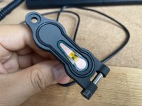
Unlike Gen1 REAP-IR with inline battery, there is only one aftermarket option to use external battery with Gen2 devices, while it is plug-and-play, I wasn't quite happy with the fact that the cable has to be routed between the battery cover and main compartment, especially when there's a waterproof seal in between the two parts.

So decided to make my own, and here's a quick prototype of my design.

The replacement cover has a PCB with two contact points, one making contact with the positive terminal of the dummy battery, which connect to device's negative, another making contact with the two middle pins, which is device's positive.
391B034A-4618-411F-BF16-76D9781B995A - Copy.jpeg


The USB cable's power outputs are connected to the PCB, and comes out on the backside of the cover. I'm only prototyping this with 3D prints at the moment, but a waterproof seal can be added like the factory cover, and where USB cable comes out can also be sealed.
16DF4F0B-B4F8-472A-9A86-CA975E06B38D - Copy.jpeg


A quick test with USB battery bank - while the two CR123a batteries in Gen2 devices are configured in parallel, supplying 3V to the device, the internal circuit remains the same as Gen1, which can accept 1 or 2 CR123a batteries in series, supplying either 3V or 6V. You can see that when supplying 5V from the USB battery bank, two battery icons are shown.
CCC8C2A1-C51B-4422-B72E-652B5C0925E9 - Copy.jpeg
 
Moving to prototyping with aluminum - which is the material the cover will be made in eventually. Also added slot for waterproof seal just like the factory cover.

IMG_4839 - Copy.jpg
 
  • Like
Reactions: stefan73
Nicely done. Not sure how complicated it is to add the circuitry, but it’s amazing how such a simple solution is so valuable.
The plan is to make a replacement cover with cable/circuitry included, so you just need to remove the factory cover, install the replacement, plug into any USB power bank and be good go to.
 
This is awesome!
But Ive got to know, how did you remove the hinge pins? On the Reaps we had the pins for the battery door were started from the inside. Thus being non removable unless you removed the battery compartment, which is why we ultimately went the way we did with the Reba adapter.
 
This is awesome!
But Ive got to know, how did you remove the hinge pins? On the Reaps we had the pins for the battery door were started from the inside. Thus being non removable unless you removed the battery compartment, which is why we ultimately went the way we did with the Reba adapter.

Yes with the replacement cover approach, it's not drop-in ready, but it's not too hard either:

One'd need to remove 4 screws for the joystick, then another for from the inside for the battery compartment, then the batter cover can be removed. All screws don't have any thread locker, there's no permeant seal to be broken. I plan to make a quick video showing how.

So while a little more effort, I think it's doable, and for people who prefer not to, then they'd have the REBA adapter, choice is always good. :)
 
  • Like
Reactions: Frog05
Yes with the replacement cover approach, it's not drop-in ready, but it's not too hard either:

One'd need to remove 4 screws for the joystick, then another for from the inside for the battery compartment, then the batter cover can be removed. All screws don't have any thread locker, there's no permeant seal to be broken. I plan to make a quick video showing how.

So while a little more effort, I think it's doable, and for people who prefer not to, then they'd have the REBA adapter, choice is always good. :)
Bravo sir! We thought it would it would be a pretty straight forward procedure, I just didn’t have the cajones to actually try it. 😂

This solution was long over due, great work!
 
Getting there...
 

Attachments

  • IMG_5031.jpeg
    IMG_5031.jpeg
    164.2 KB · Views: 68
  • IMG_5032.jpeg
    IMG_5032.jpeg
    145.6 KB · Views: 68
Getting PCB made, I have two designs, one for surface solder and another through hole, so next is to test which one works better with some stress test.
 

Attachments

  • IMG_6218.jpg
    IMG_6218.jpg
    1.1 MB · Views: 56
  • Like
Reactions: Duc and stefan73