Join the Hide community
Get access to live stream, lessons, the post exchange, and chat with other snipers.
Register
Download Gravity Ballistics
Get help to accurately calculate and scope your sniper rifle using real shooting data.

Install the app
How to install the app on iOS
Follow along with the video below to see how to install our site as a web app on your home screen.
Note: This feature may not be available in some browsers.
You are using an out of date browser. It may not display this or other websites correctly.
You should upgrade or use an alternative browser.
You should upgrade or use an alternative browser.
Gunsmithing Our latest barrel fluting effort.
- Thread starter LRI
- Start date
Between honeycomb and the new one......I have been planning on a 300NM build and have been thinking about some weight reduction.... I'll hit you up on it for pricing.
Just look on the store. They are both listed there. Gain twist fluting is also up now.
GUNSMITHING SERVICES: Barrel Fluting
Weight reduction. Probably the single most asked question regarding fluting a barrel. We recognize the need for lighter weight guns where every ounce counts. Use our online fluting calculator above to give an approximate estimate of the amount of weight reduction you can expect from having...
www.longriflesinc.com
I agree that it would be a waste on my match rifle, but not every rifle I own goes through barrels like that.I go through too many barrels to spend extra on fancy fluting but this looks really cool
Cheers
At first look I said, that looks like brick work. Very cool.
What is the needed barrel profile for this?
What is the needed barrel profile for this?
At first look I said, that looks like brick work. Very cool.
What is the needed barrel profile for this?
The biggest trick with this style of fluting is the barrel has to maintain a very consistent taper -- not all barrels do -- or the distance between pockets could end up visibly "wonky".
The larger the profile the more aggressively it can be fluted, but this could be done to almost any profile, the pockets just get more shallow.
Last edited:
When can I send you my barrel!
This service has been listed now on our site. It'll walk you through the entire process.
Happy to help.
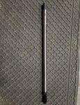
So, we did a little weight evaluation on this.
The barrel with the latest flute pattern (I'm calling it "pattern X" as we've still not settled on anything that sticks yet) began life as an "LRI Remington Varmint". All that means is its a conventional RV with one inch of cylinder added on the "big" end.
From that blank, we threaded, chambered, chopped it down to 20" and put threads on the muzzle. Then we fluted it. Once completed, we were within 3oz of a SIXTEEN inch Proof Research carbon wrapped barrel of the same caliber, contour, and twist rate.
Now, keep in mind. We left the extra inch worth of cylinder on the muzzle. Trim that off and the weight differential becomes less than 4, 300 grain Sierra bullets.
Anyways, there's that.
Had one done from Twisted Barrel that is close to yours. I believe it was called Interupted Spiral, but that's been a few years ago.No idea what to call it, but I love it. I don't get too spun up on barrel stuff anymore, but this one hits home for some reason.
Kaylyb and Sam had been working on this last few days at night. I dig it.
Nice work germs!
View attachment 7161295
View attachment 7161296
View attachment 7161297
Had one done from Twisted Barrel that is close to yours. I believe it was called Interupted Spiral, but that's been a few years ago.
I'm going to sound like I'm splitting hairs here.
For those who don't do this stuff, some cnc basics:
We want to go from point A to point B feeding a tool at "whatever" inches per minute at "whatever" spindle rpm. Looks something like this:
T1M6
G0 X0.Y0.
M3S2500 ("G0" is FANUC for rapid. X/Y are axis direction (+/-) and the numbers are locations. T1 is the tool number in the machine. You set this however you want. M3 is clockwise rotation at 2500rpm.) -can't have two "M" codes on the same block.
There's some other shit that would go in here like tool height offset callups, work offsets, safety lines, etc. -Keeping this simple.
G94 G1 X-10. Y-.6 F27 (G94 tells the machine to move in "inches per minute". G1 is a feedrate. The "rate" is 27 inches per minute set by the "F27". X is going to move from right to left 10 inches simultaneous to the Y movingaway from you around 5/8 of an inch.
So, you just whittled a crooked straight line. No big deal. Now put a "twist in that line".
T1M6
G0 X0.Y0.A0.
M3S2500 (Same code, but now we have an A axis start point thrown in)
G1 X-10.Y-.6A180.F27 (Again, same fundamental code, but now with an A axis end point added)
Were moving in the same direction as the first one, but now were rotating the object as we move. When your done, you have a single helical groove wrapping around the object for half of a rotation.
Pretty simple. The machine does the "real" work. How you setup parameters for axis control matters here. Very possible to outrun the "A" if we were to put the hammer down on the X/Y moves. One always has to be aware of the max feed rate possible of the weakest link. Otherwise you end up with a funny looking feature at the end where the X/Y have stopped, but the A is still rotating. Older machines were plagued with this. We are constrained to a single feedrate per block of code. Simply to mean I cannot make one axis move faster than another on a single line.
G1X-10.F250 Y-.6F75 A180.F400. (This would never work in a machine. It would alarm instantly and tell you go unfuck yourself.
") )
)-keep this information in your head, it'll be more relevant shortly.
Now, a skipping type groove. I'll pencil out a short n sweet version of this:
First, some basic math.
180/10=18 For every inch of linear travel the part rotates 18*.
.6 in Y/10=.06 Total travel of Y broken down into per inch segements.
T1M6
G0X.0Y0.A0.
M3S2500
G1X-2.5Y-.15A45.
Y-1.0 (Get tool out of part)
G0X-5.0A90. (rapid to next entry position in X and A.)
G1Y-.3 (back in feed mode and entering the part at the predicted position
X-7.5Y-.45A135. ("G1" is a modal command so machine stays in state last told (by previous block of code above)
This would go on and on. In, feed/twist, out, rapid to start, feed, feed/twist, etc...
Not too big a deal.
Now, where we get busy:
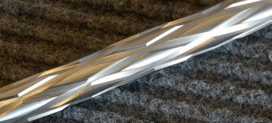
Were not just "morse coding" down the side of a stick. Each segement is a pocket. That in itself is no big deal either. Where the "kink" comes into play is when you generate these pockets using all 4 axis's of the machine. If you look closely in our photos, the bottom of the pocket is smaller in cross section than the top. The bottom of the endmill is not machining a "box". The floor is not flat. It's curved to emulate taking a pair of really kinky bedroom stockings and sliding it over an existing barrel. "Growing" it I guess you'd call it to look like what we have.
It's software driven. Even with some clever macros it would be a very code intensive thing to try and "fat finger" out on a control screen. Because were not making straight lines and arcs, we get into the world of spline generation. This is both in the code and in how the software manages the geometry you see on the screen.
Splines are not lines and they are not arcs. Splines get their behavior from shipyards 3-4-5 hundred years ago. Its a computer generated piece of geometry designed to emulate how a board behaves when its joined to the substructure of a wooden ship. -kinda cool.
Example. An "arc" has a start, an end, and a center point. That's it. A splined arc is bunch of short line segments connected to form a circle. The resolution of the spline is something you dictate in the software. Where this becomes a bigger deal is in code generation for the machine. Efficient use of code was once a big deal due to memory constraints. It's far less "busy" and easy to keep track of a single arc movement on a single block of code vs what would easily turn into an almost infinite number of lines for the same movment. The only real means of getting from point A to point B while also doing all this other stuff is to break that code into very short segments. Remember, we can only move at a single feedrate per block of code. If I need to get from here to there but it requires a great deal of motion in one particular direction to do it, I have to be very careful how it generate those instructions. Not at all uncommon to see stuff where the machine is running along at say, 30ipm, then it creates an A move at something north of 600ipm. Freaks you out when your first getting exposure to this, till you realize the machine actually only moved maybe .0006" of an inch. Those kinds of motions create their set of challenges because of how the machine uses that data.
Older machines had DC servos that just struggled to move in very small multiples. start, stop, start, stop, start, stop... Combine that with the buffer limitations of the hardware in the machine. Long story short, you either run stuff super, super slow, or you let your machine beat the snot out of itself from the servos slamming as they try to machine this feature you programmed.
Newer stuff deals with this much, much better and most have an "overwatch" of sorts that prevents you from banging the shit out of ballscrews and whatnot. The 1990's and early 2000's were more of a lawless wasteland.
Take all this in, were now moving in X, Y, Z, and A simultaniously to generate little pockets in a helical format that grow outward from center. Then we chamfer them on a cylindrical body that is altering its shape in a taper.
With the understanding that the next one we do right behind it, will be different and require editing.
What were doing is not "rocket science" or some exclusive thing that nobody else could ever hope to achieve. Not even close. That said, in the little game we play here, it's unique. To my knowledge we are the first to offer something like this. My only hope in this long response is to convey some of the work that goes into this as its not a trivial thing to do and its not even remotely similar to anything I've ever seen offered previously.
Last edited:
How difficult is it to do from the gas block forward. I'm thinking about it on my 243 LBC build. Standard barrel profile.I'm going to sound like I'm splitting hairs here.
For those who don't do this stuff, some cnc basics:
We want to go from point A to point B feeding a tool at "whatever" inches per minute at "whatever" spindle rpm. Looks something like this:
G0 X0.Y0. T1M6
M3S2500 ("G0" is FANUC for rapid. X/Y are axis direction (+/-) and the numbers are locations. T1 is the tool number in the machine. You set this however you want. M3 is clockwise rotation at 2500rpm.) -can't have two "M" codes on the same block.
There's some other shit that would go in here like tool height offset callups, work offsets, safety lines, etc. -Keeping this simple.
G94 G1 X-10. Y-.6 F27 (G94 tells the machine to move in "inches per minute". G1 is a feedrate. The "rate" is 27 inches per minute set by the "F27". X is going to move from right to left 10 inches simultaneous to the Y movingaway from you around 5/8 of an inch.
So, you just whittled a crooked straight line. No big deal. Now put a "twist in that line".
G0 X0.Y0.A0. T1M6
M3S2500 (Same code, but now we have an A axis start point thrown in)
G1 X-10.Y-.6A180.F27 (Again, same fundamental code, but now with an A axis end point added)
Were moving in the same direction as the first one, but now were rotating the object as we move. When your done, you have a single helical groove wrapping around the object for half of a rotation.
Pretty simple. The machine does the "real" work. How you setup parameters for axis control matters here. Very possible to outrun the "A" if we were to put the hammer down on the X/Y moves. One always has to be aware of the max feed rate possible of the weakest link. Otherwise you end up with a funny looking feature at the end where the X/Y have stopped, but the A is still rotating. Older machines were plagued with this. We are constrained to a single feedrate per block of code. Simply to mean I cannot make one axis move faster than another on a single line.
G1X-10.F250 Y-.6F75 A180.F400. (This would never work in a machine. It would alarm instantly and tell you go unfuck yourself.
-keep this information in your head, it'll be more relevant shortly.
Now, a skipping type groove. I'll pencil out a short n sweet version of this:
First, some basic math.
180/10=18 For every inch of linear travel the part rotates 18*.
.6 in Y/10=.06 Total travel of Y broken down into per inch segements.
G0X.0Y0.A0. T1M6
M3S2500
G1X-2.5Y-.15A45.
Y-1.0 (Get tool out of part)
G0X-5.0A90. (rapid to next entry position in X and A.)
G1Y-.3 (back in feed mode and entering the part at the predicted position
X-7.5Y-.45A135. ("G1" is a modal command so machine stays in state last told (by previous block of code above)
This would go on and on. In, feed/twist, out, rapid to start, feed, feed/twist, etc...
Not too big a deal.
Now, where we get busy:
Were not just "morse coding" down the side of a stick. Each segement is a pocket. That in itself is no big deal either. Where the "kink" comes into play is when you generate these pockets using all 4 axis's of the machine. If you look closely in our photos, the bottom of the pocket is smaller in cross section than the top. The bottom of the endmill is not machining a "box". The floor is not flat. It's curved to emulate taking a pair of really kinky bedroom stockings and sliding it over an existing barrel. "Growing" it I guess you'd call it to look like what we have.
It's software driven. Even with some clever macros it would be a very code intensive thing to try and "fat finger" out on a control screen. Because were not making straight lines and arcs, we get into the world of spline generation. This is both in the code and in how the software manages the geometry you see on the screen.
Splines are not lines and they are not arcs. Splines get their behavior from shipyards 3-4-5 hundred years ago. Its a computer generated piece of geometry designed to emulate how a board behaves when its joined to the substructure of a wooden ship. -kinda cool.
Example. An "arc" has a start, an end, and a center point. That's it. A splined arc is bunch of short line segments connected to form a circle. The resolution of the spline is something you dictate in the software. Where this becomes a bigger deal is in code generation for the machine. Efficient use of code was once a big deal due to memory constraints. It's far less "busy" and easy to keep track of a single arc movement on a single block of code vs what would easily turn into an almost infinite number of lines for the same movment. The only real means of getting from point A to point B while also doing all this other stuff is to break that code into very short segments. Remember, we can only move at a single feedrate per block of code. If I need to get from here to there but it requires a great deal of motion in one particular direction to do it, I have to be very careful how it generate those instructions. Not at all uncommon to see stuff where the machine is running along at say, 30ipm, then it creates an A move at something north of 600ipm. Freaks you out when your first getting exposure to this, till you realize the machine actually only moved maybe .0006" of an inch. Those kinds of motions create their set of challenges because of how the machine uses that data.
Older machines had DC servos that just struggled to move in very small multiples. start, stop, start, stop, start, stop... Combine that with the buffer limitations of the hardware in the machine. Long story short, you either run stuff super, super slow, or you let your machine beat the snot out of itself from the servos slamming as they try to machine this feature you programmed.
Newer stuff deals with this much, much better and most have an "overwatch" of sorts that prevents you from banging the shit out of ballscrews and whatnot. The 1990's and early 2000's were more of a lawless wasteland.
Take all this in, were now moving in X, Y, Z, and A simultaniously to generate little pockets in a helical format that grow outward from center. Then we chamfer them on a cylindrical body that is altering its shape in a taper.
With the understanding that the next one we do right behind it, will be different and require editing.
What were doing is not "rocket science" or some exclusive thing that nobody else could ever hope to achieve. Not even close. That said, in the little game we play here, it's unique. To my knowledge we are the first to offer something like this. My only hope in this long response is to convey some of the work that goes into this as its not a trivial thing to do and its not even remotely similar to anything I've ever seen offered previously.
How difficult is it to do from the gas block forward. I'm thinking about it on my 243 LBC build. Standard barrel profile.
The work at the computer is really about the same. Only savings is its typically going to be a shorter tool path just because the length is smaller.
I'm going to sound like I'm splitting hairs here.
For those who don't do this stuff, some cnc basics:
We want to go from point A to point B feeding a tool at "whatever" inches per minute at "whatever" spindle rpm. Looks something like this:
T1M6
G0 X0.Y0.
M3S2500 ("G0" is FANUC for rapid. X/Y are axis direction (+/-) and the numbers are locations. T1 is the tool number in the machine. You set this however you want. M3 is clockwise rotation at 2500rpm.) -can't have two "M" codes on the same block.
There's some other shit that would go in here like tool height offset callups, work offsets, safety lines, etc. -Keeping this simple.
G94 G1 X-10. Y-.6 F27 (G94 tells the machine to move in "inches per minute". G1 is a feedrate. The "rate" is 27 inches per minute set by the "F27". X is going to move from right to left 10 inches simultaneous to the Y movingaway from you around 5/8 of an inch.
So, you just whittled a crooked straight line. No big deal. Now put a "twist in that line".
T1M6
G0 X0.Y0.A0.
M3S2500 (Same code, but now we have an A axis start point thrown in)
G1 X-10.Y-.6A180.F27 (Again, same fundamental code, but now with an A axis end point added)
Were moving in the same direction as the first one, but now were rotating the object as we move. When your done, you have a single helical groove wrapping around the object for half of a rotation.
Pretty simple. The machine does the "real" work. How you setup parameters for axis control matters here. Very possible to outrun the "A" if we were to put the hammer down on the X/Y moves. One always has to be aware of the max feed rate possible of the weakest link. Otherwise you end up with a funny looking feature at the end where the X/Y have stopped, but the A is still rotating. Older machines were plagued with this. We are constrained to a single feedrate per block of code. Simply to mean I cannot make one axis move faster than another on a single line.
G1X-10.F250 Y-.6F75 A180.F400. (This would never work in a machine. It would alarm instantly and tell you go unfuck yourself.
-keep this information in your head, it'll be more relevant shortly.
Now, a skipping type groove. I'll pencil out a short n sweet version of this:
First, some basic math.
180/10=18 For every inch of linear travel the part rotates 18*.
.6 in Y/10=.06 Total travel of Y broken down into per inch segements.
T1M6
G0X.0Y0.A0.
M3S2500
G1X-2.5Y-.15A45.
Y-1.0 (Get tool out of part)
G0X-5.0A90. (rapid to next entry position in X and A.)
G1Y-.3 (back in feed mode and entering the part at the predicted position
X-7.5Y-.45A135. ("G1" is a modal command so machine stays in state last told (by previous block of code above)
This would go on and on. In, feed/twist, out, rapid to start, feed, feed/twist, etc...
Not too big a deal.
Now, where we get busy:
Were not just "morse coding" down the side of a stick. Each segement is a pocket. That in itself is no big deal either. Where the "kink" comes into play is when you generate these pockets using all 4 axis's of the machine. If you look closely in our photos, the bottom of the pocket is smaller in cross section than the top. The bottom of the endmill is not machining a "box". The floor is not flat. It's curved to emulate taking a pair of really kinky bedroom stockings and sliding it over an existing barrel. "Growing" it I guess you'd call it to look like what we have.
It's software driven. Even with some clever macros it would be a very code intensive thing to try and "fat finger" out on a control screen. Because were not making straight lines and arcs, we get into the world of spline generation. This is both in the code and in how the software manages the geometry you see on the screen.
Splines are not lines and they are not arcs. Splines get their behavior from shipyards 3-4-5 hundred years ago. Its a computer generated piece of geometry designed to emulate how a board behaves when its joined to the substructure of a wooden ship. -kinda cool.
Example. An "arc" has a start, an end, and a center point. That's it. A splined arc is bunch of short line segments connected to form a circle. The resolution of the spline is something you dictate in the software. Where this becomes a bigger deal is in code generation for the machine. Efficient use of code was once a big deal due to memory constraints. It's far less "busy" and easy to keep track of a single arc movement on a single block of code vs what would easily turn into an almost infinite number of lines for the same movment. The only real means of getting from point A to point B while also doing all this other stuff is to break that code into very short segments. Remember, we can only move at a single feedrate per block of code. If I need to get from here to there but it requires a great deal of motion in one particular direction to do it, I have to be very careful how it generate those instructions. Not at all uncommon to see stuff where the machine is running along at say, 30ipm, then it creates an A move at something north of 600ipm. Freaks you out when your first getting exposure to this, till you realize the machine actually only moved maybe .0006" of an inch. Those kinds of motions create their set of challenges because of how the machine uses that data.
Older machines had DC servos that just struggled to move in very small multiples. start, stop, start, stop, start, stop... Combine that with the buffer limitations of the hardware in the machine. Long story short, you either run stuff super, super slow, or you let your machine beat the snot out of itself from the servos slamming as they try to machine this feature you programmed.
Newer stuff deals with this much, much better and most have an "overwatch" of sorts that prevents you from banging the shit out of ballscrews and whatnot. The 1990's and early 2000's were more of a lawless wasteland.
Take all this in, were now moving in X, Y, Z, and A simultaniously to generate little pockets in a helical format that grow outward from center. Then we chamfer them on a cylindrical body that is altering its shape in a taper.
With the understanding that the next one we do right behind it, will be different and require editing.
What were doing is not "rocket science" or some exclusive thing that nobody else could ever hope to achieve. Not even close. That said, in the little game we play here, it's unique. To my knowledge we are the first to offer something like this. My only hope in this long response is to convey some of the work that goes into this as its not a trivial thing to do and its not even remotely similar to anything I've ever seen offered previously.
When you watch it on video the guy just pushes the start button and the machine cuts the shapes out, lol.
Hand editing g code, now there's some fun.
Speeds, feeds, rapid traverse, depth increments. Trying to save tools and cut time as well as have a nice finish.
My parts were 3D (axis) toss in 2 more axis.
No thanks.
Most people will not conceive the difficulty in the process. Set up and run times on one off parts, thats what your paying for.
Speeds, feeds, rapid traverse, depth increments. Trying to save tools and cut time as well as have a nice finish.
My parts were 3D (axis) toss in 2 more axis.
No thanks.
Most people will not conceive the difficulty in the process. Set up and run times on one off parts, thats what your paying for.
@LongRifles Inc.
I have a DT SRS A1 aftermarket barrel I’d like you to do. Is this pattern possible?
Barrel is 1.045 contour.
thanks

I have a DT SRS A1 aftermarket barrel I’d like you to do. Is this pattern possible?
Barrel is 1.045 contour.
thanks
Is the object of this exercise to not only lessen weight but also to increase surface area? If so i seem to recall from biology that a villous pattern exhibits a very high surface area to volume....I guess you wouldn't want a fragile pattern so maybe something blunted kind of like velcro?
@LongRifles Inc.
I have a DT SRS A1 aftermarket barrel I’d like you to do. Is this pattern possible?
Barrel is 1.045 contour.
thanks
View attachment 7184422
If it's concentric it can be fluted, so it shouldn't be a problem. We only flute the taper, we don't get into the "neck".
Chinese finger trap
"Fingercuffs." Now I have "Chasing Amy" stuck in my head.
Thanks.... Jay and Silent Bob...
REALLY?
lol.
You're welcome ??"Fingercuffs." Now I have "Chasing Amy" stuck in my head.
Thanks.... Jay and Silent Bob...
REALLY?
lol.
@sjg
Ya I’d only want it back to the ridged shoulder.
Let me know and if you give the green light, I’ll ship it out.
That will be no problem.
How long did that take to machine?
Do you include the time the CNC machine is doing it's thing after you push the start button?
By starting with such a large diameter blank and removing material so deep while leaving the structural web at a large diameter you maximize your stiffness to weight ratio. Most fluting I consider more for looks than function but this one removes a lot of weight while keeping it stiff. --Jerry
very innovative Chad.No idea what to call it, but I love it. I don't get too spun up on barrel stuff anymore, but this one hits home for some reason.
Kaylyb and Sam had been working on this last few days at night. I dig it.
Nice work germs!
View attachment 7161295
View attachment 7161296
View attachment 7161297
The first time I saw this I knew it was special. I poured over the photos and could see some of these machining features you mention. This appears to me to be the most thoroughly thought out fluting ever devised.I'm going to sound like I'm splitting hairs here.
For those who don't do this stuff, some cnc basics:
We want to go from point A to point B feeding a tool at "whatever" inches per minute at "whatever" spindle rpm. Looks something like this:
T1M6
G0 X0.Y0.
M3S2500 ("G0" is FANUC for rapid. X/Y are axis direction (+/-) and the numbers are locations. T1 is the tool number in the machine. You set this however you want. M3 is clockwise rotation at 2500rpm.) -can't have two "M" codes on the same block.
There's some other shit that would go in here like tool height offset callups, work offsets, safety lines, etc. -Keeping this simple.
G94 G1 X-10. Y-.6 F27 (G94 tells the machine to move in "inches per minute". G1 is a feedrate. The "rate" is 27 inches per minute set by the "F27". X is going to move from right to left 10 inches simultaneous to the Y movingaway from you around 5/8 of an inch.
So, you just whittled a crooked straight line. No big deal. Now put a "twist in that line".
T1M6
G0 X0.Y0.A0.
M3S2500 (Same code, but now we have an A axis start point thrown in)
G1 X-10.Y-.6A180.F27 (Again, same fundamental code, but now with an A axis end point added)
Were moving in the same direction as the first one, but now were rotating the object as we move. When your done, you have a single helical groove wrapping around the object for half of a rotation.
Pretty simple. The machine does the "real" work. How you setup parameters for axis control matters here. Very possible to outrun the "A" if we were to put the hammer down on the X/Y moves. One always has to be aware of the max feed rate possible of the weakest link. Otherwise you end up with a funny looking feature at the end where the X/Y have stopped, but the A is still rotating. Older machines were plagued with this. We are constrained to a single feedrate per block of code. Simply to mean I cannot make one axis move faster than another on a single line.
G1X-10.F250 Y-.6F75 A180.F400. (This would never work in a machine. It would alarm instantly and tell you go unfuck yourself.
-keep this information in your head, it'll be more relevant shortly.
Now, a skipping type groove. I'll pencil out a short n sweet version of this:
First, some basic math.
180/10=18 For every inch of linear travel the part rotates 18*.
.6 in Y/10=.06 Total travel of Y broken down into per inch segements.
T1M6
G0X.0Y0.A0.
M3S2500
G1X-2.5Y-.15A45.
Y-1.0 (Get tool out of part)
G0X-5.0A90. (rapid to next entry position in X and A.)
G1Y-.3 (back in feed mode and entering the part at the predicted position
X-7.5Y-.45A135. ("G1" is a modal command so machine stays in state last told (by previous block of code above)
This would go on and on. In, feed/twist, out, rapid to start, feed, feed/twist, etc...
Not too big a deal.
Now, where we get busy:
Were not just "morse coding" down the side of a stick. Each segement is a pocket. That in itself is no big deal either. Where the "kink" comes into play is when you generate these pockets using all 4 axis's of the machine. If you look closely in our photos, the bottom of the pocket is smaller in cross section than the top. The bottom of the endmill is not machining a "box". The floor is not flat. It's curved to emulate taking a pair of really kinky bedroom stockings and sliding it over an existing barrel. "Growing" it I guess you'd call it to look like what we have.
It's software driven. Even with some clever macros it would be a very code intensive thing to try and "fat finger" out on a control screen. Because were not making straight lines and arcs, we get into the world of spline generation. This is both in the code and in how the software manages the geometry you see on the screen.
Splines are not lines and they are not arcs. Splines get their behavior from shipyards 3-4-5 hundred years ago. Its a computer generated piece of geometry designed to emulate how a board behaves when its joined to the substructure of a wooden ship. -kinda cool.
Example. An "arc" has a start, an end, and a center point. That's it. A splined arc is bunch of short line segments connected to form a circle. The resolution of the spline is something you dictate in the software. Where this becomes a bigger deal is in code generation for the machine. Efficient use of code was once a big deal due to memory constraints. It's far less "busy" and easy to keep track of a single arc movement on a single block of code vs what would easily turn into an almost infinite number of lines for the same movment. The only real means of getting from point A to point B while also doing all this other stuff is to break that code into very short segments. Remember, we can only move at a single feedrate per block of code. If I need to get from here to there but it requires a great deal of motion in one particular direction to do it, I have to be very careful how it generate those instructions. Not at all uncommon to see stuff where the machine is running along at say, 30ipm, then it creates an A move at something north of 600ipm. Freaks you out when your first getting exposure to this, till you realize the machine actually only moved maybe .0006" of an inch. Those kinds of motions create their set of challenges because of how the machine uses that data.
Older machines had DC servos that just struggled to move in very small multiples. start, stop, start, stop, start, stop... Combine that with the buffer limitations of the hardware in the machine. Long story short, you either run stuff super, super slow, or you let your machine beat the snot out of itself from the servos slamming as they try to machine this feature you programmed.
Newer stuff deals with this much, much better and most have an "overwatch" of sorts that prevents you from banging the shit out of ballscrews and whatnot. The 1990's and early 2000's were more of a lawless wasteland.
Take all this in, were now moving in X, Y, Z, and A simultaniously to generate little pockets in a helical format that grow outward from center. Then we chamfer them on a cylindrical body that is altering its shape in a taper.
With the understanding that the next one we do right behind it, will be different and require editing.
What were doing is not "rocket science" or some exclusive thing that nobody else could ever hope to achieve. Not even close. That said, in the little game we play here, it's unique. To my knowledge we are the first to offer something like this. My only hope in this long response is to convey some of the work that goes into this as its not a trivial thing to do and its not even remotely similar to anything I've ever seen offered previously.
Reviving this thread, such a cool fluting pattern!
@LongRifles Inc., any idea what the weight on a 16" MTU contour barrel (6.5mm bore) with this fluting would be?
My original precision rifle is sitting in my gun room collecting dust, debating about turning it into a hunting rifle. It has an essentially brand new 24" 1:7 twist hawkhill barrel on it. Trying to determine if this barreled action with this fluting pattern could make a reasonable(ish) hunting rifle.
Kind of reminds me of a field cultivator basket. Call it the "cultivator cut".

I always think this is cool, then I imagine myself sitting down with cotton swabs after shooting in the dust all day to clean it and I'm lazy
I always think this is cool, then I imagine myself sitting down with cotton swabs after shooting in the dust all day to clean it and I'm lazy
Dude, buy stainless and run it through the dishwasherKind of reminds me of a field cultivator basket. Call it the "cultivator cut".
View attachment 7856407
I always think this is cool, then I imagine myself sitting down with cotton swabs after shooting in the dust all day to clean it and I'm lazy
I always think this is cool, then I imagine myself sitting down with cotton swabs after shooting in the dust all day to clean it and I'm lazy
Just ceracoat the cuts only with a nice olive drab or FDE and forget about cleaning those slots…
Follow me for more cleaning tips.

Cleaning ? Dude, just buy another gun if it get dirty.
Go be poor somewhere else.
Go be poor somewhere else.
Oh man, that one's got removable chokes!
Oh man, that one's got removable chokes!
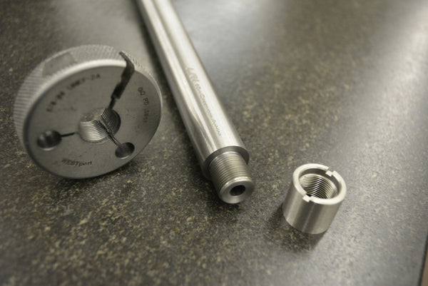
LRI Custom Fitted Thread Protectors
Our thread protectors are designed to serve a dual purpose. When installed they alter the muzzle to emulate a recessed muzzle crown typical of a sporting type rifle. This provides additional insurance against accidental damage. The innovative notch at the front facilitates easy removal and...
www.longriflesinc.com
Similar threads
- Replies
- 0
- Views
- 2K
- Replies
- 5
- Views
- 627
- Replies
- 108
- Views
- 3K
