
After a fair amount of research its come to my attention that there's some artistic interpretation on this process. Prints are scarce and even after tracking down some old salts from PWS there's still some rather vague/grey areas that were often left to the whims of the person doing the work.
I'm not a historian on the M40 by any means. I generally take my cues on this stuff from a neighbor who's forgotten more about it than I'll ever know. After speaking with him at length yesterday, here's what I came up with.
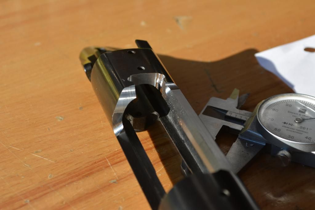
The question I had is based off the print I was given. There are missing dimensions. Specifically the pair of tangent radius features where the bridge transitions back to the OEM port length. Same goes for the opposite side. The drawing clearly shows the facets on the side opposite of the port continuing back to the bridge, despite the lack of dimension callouts.
When I confronted Al, he smirked and simply replied, "there's no hard rule on this. Everyone was doing these things back in the day..." He went on to comment about how the port elongation varies between two different types as well. The double radius that I did and the single large radius. Both are correct, just a matter of who did it.
So, I wing'd it.") Came out perty nice I think. I did this one completely by hand on the Bridgeport. If I get more I'll prolly fixture it up in the 4th axis and automate the process.
Came out perty nice I think. I did this one completely by hand on the Bridgeport. If I get more I'll prolly fixture it up in the 4th axis and automate the process.
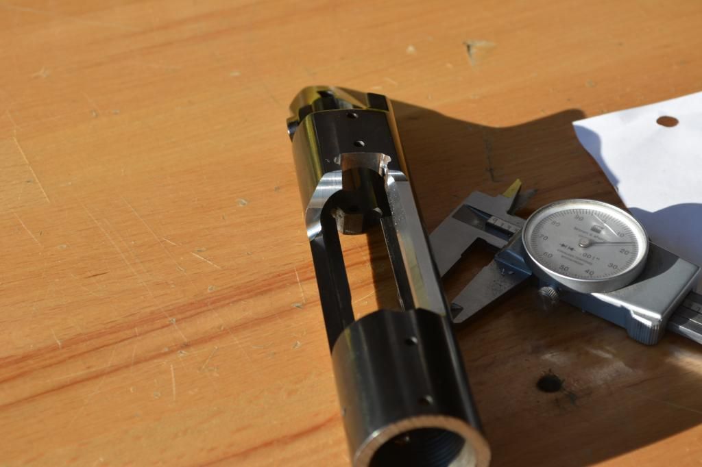
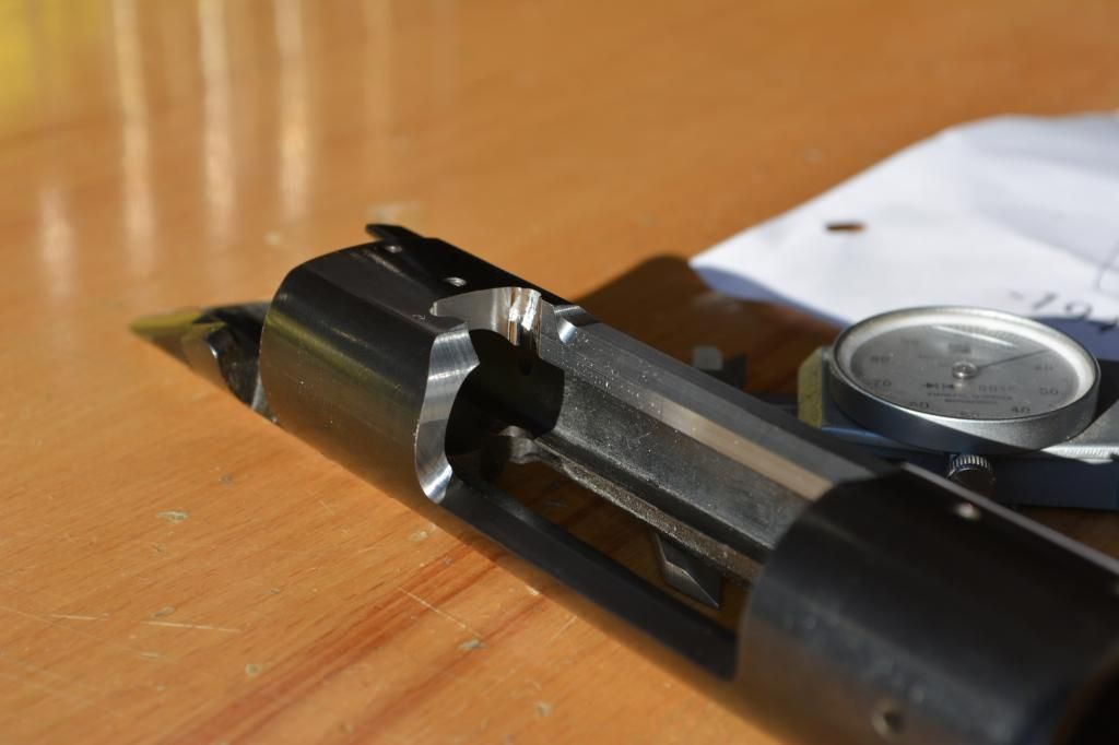
I elected to run the port radius features all the way down to the ejection port floor as the receiver wasn't quite square here and I had a funny edge initially where the tool exited the part. continuing it down to the port floor corner radius made for a convenient transition point that once finished should make for a nice looking piece.
Base holes on this action were spot on. The owner sourced this receiver and he did a great job. All the holes were within .002" of the raceway centerline. Made my job much, much easier.
All that's left is a little engraving on the action and barrel.
Neat stuff!
C.
I'm not a historian on the M40 by any means. I generally take my cues on this stuff from a neighbor who's forgotten more about it than I'll ever know. After speaking with him at length yesterday, here's what I came up with.
The question I had is based off the print I was given. There are missing dimensions. Specifically the pair of tangent radius features where the bridge transitions back to the OEM port length. Same goes for the opposite side. The drawing clearly shows the facets on the side opposite of the port continuing back to the bridge, despite the lack of dimension callouts.
When I confronted Al, he smirked and simply replied, "there's no hard rule on this. Everyone was doing these things back in the day..." He went on to comment about how the port elongation varies between two different types as well. The double radius that I did and the single large radius. Both are correct, just a matter of who did it.
So, I wing'd it.
Came out perty nice I think. I did this one completely by hand on the Bridgeport. If I get more I'll prolly fixture it up in the 4th axis and automate the process.I elected to run the port radius features all the way down to the ejection port floor as the receiver wasn't quite square here and I had a funny edge initially where the tool exited the part. continuing it down to the port floor corner radius made for a convenient transition point that once finished should make for a nice looking piece.
Base holes on this action were spot on. The owner sourced this receiver and he did a great job. All the holes were within .002" of the raceway centerline. Made my job much, much easier.
All that's left is a little engraving on the action and barrel.
Neat stuff!
C.

