• Watch Out for Scammers!

    We've now added a color code for all accounts. Orange accounts are new members, Blue are full members, and Green are Supporters. If you get a message about a sale from an orange account, make sure you pay attention before sending any money!

Gunsmithing homemade paint oven (more pics added)

Re: homemade paint oven (more pics added)

What a neat little thread this is!

Consider this a tag for future reading
laugh.gif
 
Re: homemade paint oven (more pics added)

I didn't remember using any of the silicon on the sides. Its all compression fit. I cut the panels a little over sized. I used the box its self for the template. Just laid it down on the board and cut around it. So the finished cut was just a little bigger than the inside dimensions. The top has bolts going through it so its not coming down plus with the silicon at every seam, its not coming apart.

I did use a little silicon on the door panel since I couldn't really get a good cut on it. Another thing the silicon helps with is the fiberglass dust. The first couple of test runs with just painted plates of steel showed dust had gotten on the finish. Now, it was easily removed and it wasn't under the finish so it came from the oven. The silicon in the corners and ever spot fiberglass was visible. That fixed the dust problem. I also have adopted the practice of vacumning out the entire oven before each use. I live in West Texas and dust can get into anything sealed. Its practically magic I assure you.

Mike
 
Re: homemade paint oven (more pics added)

Good job on your oven so far. I'm interested in this "hardi-backer" stuff you are using. Haven't seen anything like that around here. When we made ours, we just used 5/8" FireWall.

Hoping you got your PID from Auber Instruments, as they had a great selection and great customer service. With even better prices.

(shameless plug/no affiliation whatsoever/the best place to go)
 
Re: homemade paint oven (more pics added)

Pics coming up fine. Great idea on the oven, trust me if since you cannot see the pics the oven and products it has produced look great.
 
Re: homemade paint oven (more pics added)

Hardi-backer is used for ceramic tile installations. The same material is molded and formed for different applications. I used Hardi-plank siding for my house. It's in 7"x10' pieces. They make other patterns in 4'x8' sheets, 3'x5', etc. Even some trim pieces come in the stuff. Its a fiber reinforced cement mixture. Heavy and sold as water proof (to an extent), bug proof, fire proof, etc. Its a sheet of concrete.
smile.gif


I got mine at Lowes but have seen it at McCoys, and Home Depot too.

<div class="ubbcode-block"><div class="ubbcode-header">Originally Posted By: Sean the Nailer</div><div class="ubbcode-body">Good job on your oven so far. I'm interested in this "hardi-backer" stuff you are using. Haven't seen anything like that around here. When we made ours, we just used 5/8" FireWall.

Hoping you got your PID from Auber Instruments, as they had a great selection and great customer service. With even better prices.

(shameless plug/no affiliation whatsoever/the best place to go) </div></div>
 
Re: homemade paint oven (more pics added)

Thanks guys, that's helpful info. Sean, I have not pulled the trigger on the PID, still waiting on what my appliance salvage guy comes up with (and a fresh paycheck), I'll check out Auber Instruments for sure!


M1k3, I agree that I'll only need to worry about sealing the edges of the ductboard insulation in the ceiling, walls, and floor, and that their compression fit will hold them in place indefinately. My worry is with the door, as I do intend to use a double thickness (3") of insulation on the door (I made up a diagram with Paint to show the plan.)

I definately want to make sure that I have the door panels attached in some kind of headache and maintenace free fashion.

doorsealinsulation.jpg


I would love it if I could just use liberal amounts of furnace cement and/or high temp silicone since I already purchased a lot of this stuff. If I had to use bolts and fender washers, I could without too much problem, but then the heat from inside transfers straight through the bolts to the door surface-

I think I'll get bolts that extend about 1" into the unsulation, and simular inserts in between the two layers to get the best of both worlds- something like this....

doorsealinsulation-2.jpg


I'm obviously overthinking all this, and definately oversharing- thank for bearing with me- any input is welcome.

Oh yeah, and I get that my spelling sucks..
 
Re: homemade paint oven (more pics added)

Thanks to Sean the Nailer for (trying to) help me understand how I'm going to need to wire this all together..

Has made me realize how much I don't know about what I'm doing.

http://www.youtube.com/watch?v=iX3kxAA2L4Q

When I get this done, I'll post a wiring diagram to help the next guy.

Here are a few helpful links along this line.


http://www.susanminor.org/forums/showthread.php?315-PID-Controller


http://www.e-f-w.com/community/content.php?cid=5ad25bd584990c62a8215040ee6c491e


http://www.talkglass.com/forum/showthread.php?t=6889&highlight=Auber

http://www.weaponeer.net/forum/forum_posts.asp?TID=2854&KW=Auber


Re: homemade paint oven (more pics added)

Where are the racks for the pork butt and baby back ribs?

Heck, you guys could go whole hog!!
grin.gif
 
Re: homemade paint oven (more pics added)

Finished my "Barrel Oven" last week.
It is much smaller than the ones you guys have made.
Pretty much just a crate made out of 2x10s big enough to house a fixture that supports a barreled action.
All other small parts I use an old toaster oven for.

This is what I used for inspiration:
http://www272.pair.com/stevewag/heater/heater4.html
oven1.jpg


One thing that I did differently than you guys though.
I used fire rated sheet rock for insulation.
It is heavy, but you can put a torch directly to it and nothing will happen. (I tried this as an experiment.)
The sheetrock also does an exceptional job at insulating the oven too.

I will take some photos this weekend and post them up.
 
Re: homemade paint oven (more pics added)

<div class="ubbcode-block"><div class="ubbcode-header">Originally Posted By: Trental</div><div class="ubbcode-body">Where are the racks for the pork butt and baby back ribs?

Heck, you guys could go whole hog!!
grin.gif
</div></div>

+1

I was thinking the same thing.
This oven is killer. Great Idea. Let me know how it works. Looks prety simple.
 
Re: homemade paint oven (more pics added)

First of all, let me apologize to M1K3 for putting my hands all over his thread as if it where my own. Second- I want to apologize to everyone who is just looking for cool pictures and is not about reading long-winded posts.

While I consider myself exceptionally handy- the scariest part of building this oven has been about the wiring and electric. I feel compelled to post the types of things I would have LOVED to have found when I was looking for help building this oven. The good news is, setting up the electrical components of an oven like this is not rocket surgery.

After speaking with the pros at Auber Instruments and explaining my project they were very helpful in explaining what I need for this oven. I’ve come to understand (not from Auber) that many (slightly) cheaper PID’s that can be found on E-bay are cloned versions of Auber’s old models- I’d just as soon have an Eotech over an Eotech clone for about the same price- wouldn’t you?

Here’s my temperature control build list: (from Auber Instruments)
http://www.auberins.com

$42.00 SYL-2362 PID two relay (one alarm and 1 Contactor/SSR)

Auber has several PID’s and- like anything- the more bells and whistles, the more expensive. Price difference is around $5 per as you go up in models. I could have paid $5-$10 less for a lower model, but went with this one- It displays both current temp and set (desired) temp (nice to know at a glance that your oven is not going to climb up to 3000 degrees instead of the 300 you thought you set it at) etc. this one has two relay loops so that one can be used for your element relay, and the other can be used for an (overheat/underheat alarm) If you wanted to get fancy, you could wire in a timer to the other relay- (for example: set temp to 310F, then set timer to turn oven off 1 hour after the oven hits 310F) Timer would cost an extra $33 and be simple to wire.

$12.00 TC-K3MM K-type thermocouple probe (air probe) smoker oven

K-type indicates a temperature range- 0-750F, all K-type thermocouples are not created equally- need one designed to measure air temperature, some are designed to measure liquid (french fry cooker) or directly measure metal (like an injection mold) This one has a 4” narrow probe specifically designed to have a good response to changes in air temperature, and still be pretty tough (not too easy to break)

$14.50 CN-PBC302-120V 30 amp contactor (or 120V coil)

There are two types of relay controllers (device that makes/breaks the electrical connection that sends juice through your heating elements); “contactors”, and SSRs (Solid State Relays). A “contactor” is a mechanical switch that opens and closes like a light switch. Drawbacks are that it can only open or close every 20 seconds or so, and can wear out from opening and closing a gillion times. This one is designed for 120V and is rated for 30 amps.

Watts= Voltage X Amps or Watts/Amps = Volts or Watts/Volts= Amps: My oven elements are from a 1300 watt toaster oven at 120V, which means about 11Amps would cover me- or a 15Amp contactor as is sold- but am told it’s much better to run half the amps through a 30Amp contactor than full bastard through a 15Amp- will last much longer and have fewer problems.

FYI – 1800 Watts is about all you’d want to try to run off of a standard 120V power (which use a 15Amp breaker 120x15=1800). My heating elements are 1300 Watt, my oven light is 75 Watt, and my cooling fan is 150W (1.3A) for a total of 1525W . Many larger toaster ovens can pull up to 1600 watts- point being, I wouldn’t try to get too close to 1800 total Watts before considering going with a 220V system which generally run a 20amp breaker. Please correct me if I’m misunderstanding something.

FYI- An SSR (Solid State Relay) is not a mechanical switch, its entirely electronic- It can switch on and off many times per second (instead of every 20 seconds). It does not wear out like a mechanical, and can keep a more precise temperature- (basically overkill for this type of oven IMHO) There is not much price difference between a “contactor” and an SSR, but the SSR does produce a lot of heat- and needs a heat sink which costs an extra 10 bucks. ALSO- SSR is highly susceptible to power surge, it’s important to use a special fuse that is more than just a standard surge protector- or else your SSR can be toasted easily. It’s best to have a cooling fan for an SSR if it’s inside a housing, which is not required for a contactor- Since I am housing all of my wiring components in the same shell as my oven- I’ll be running a cooling fan anyway- PID, and contactor needs to stay below 150F.

You’re probably going to need a terminal strip (wire connector bus) from home depot, or radio shack. You need high temperature (fiberglass insulated) wire to wire the heating elements inside the oven- 16-12 gauge will do- cost about $1 per foot. My power cord is a 10ft (14 gauge?) 3 prong extension cord. So 14 gauge wire will do in and out, and 18 gauge is more than plenty for wiring the controller.

I hope that someone finds this post helpful, I apologize again to the rest of you. I found a great wiring diagram for a similar (smoker) oven, and changed it to include all the elements of my oven. I am not an electrician!- Do not use this diagram! For entertainment purposes only!!! You blow up your shop- don’t come crying to me!

PIDWiringdiagram-2-jpg.jpg


EDIT: blacked out PID connection ports since that will be unique to each PID, DO NOT USE THIS DIAGRAM TO WIRE YOUR PID- INFORMATIONAL PURPOSE ONLY! I AM BROKE! SUING ME FOR AFTER ELECTROCUTING YOURSELF MAKES IT DOUBLE SAD FOR YOU AS I HAVE NOTHING EXCEPT A HOMEMADE CURING OVEN TO MY NAME!
 
Re: homemade paint oven (more pics added)

sure would be nice not to have to use by BBQ to cure my Norrel molycoating....
 
Re: homemade paint oven (more pics added)

MSAHLM,

Good job. Due to the nature of this project with the application AS WELL AS the location varying so much, there are many variables.

This is why I haven't gone into great detail, as one who is going to take on a project like this would need to investigate their own directions.

Some may think this lame, but Finished Product, Fire, Electrocution, Insurance Coverage, and Liability are all issues that could come into play with a project like this. And we all know that there are rocket-surgeons out there who'd point at (this?) and say "but that's how they do it on the interweb".

So while I/we may show what we've done here, as well as point/direct others to EXTREMELY HELPFUL references, this is all on ones own initiative. And when you/they learn for yourselves/themselves, that in itself is the culmination of achievement.

And again, absolutely great start. Just didn't want anyone thinking that we're keeping secrets here, and whatnot. That, and not all of us are adept at making fancy little computer drawings, bar graphs, and tutorials.
wink.gif
 
Re: homemade paint oven (more pics added)

Nice ovens Guys! Just wondering though, why you needed a window to.....watch paint dry?
 
Re: homemade paint oven (more pics added)

No real need at all for a window (and the subsequent oven light) other than my own O-C-D compulsion to watch what's going on in there and make sure it's not having some kind of meltdown or malfunction. It's a waste of time, effort, money, and it creates a lot more engineering headaches-

Having said that- gotta have a window.
smile.gif
 
Re: homemade paint oven (more pics added)

I just now got to read this post so sorry if I'm a little late. I'm a maintenance supervisor and have a degree in systems management with specifics on electrical controls. I have been doing electrical work since I was 16, professional training not shadetree stuff, and now work on industrial 3 phase every day.

I'd be happy to help if you're uncomfortable with anything. One thing to note that a PID controller can wear out a contactor very quick as the temp controller can cycle quickly. I only use ssr for heaters even though they cost a little more. There are different qualities of these relays as well.

Also make sure you get a temp controller that has an autotune function. This will help maintaining a constant temp. I really like watlow brand. Also your fans should be interlocked to the heater in some way meaning that if they cut out then the controller will shut off.

I will post more specifics tonight when I get off of work and have more time to go through your design. Also a lot of electrical supply stores will sell to walk ins at the cadillac price which a lot of times is cheaper than eBay and you get good stuff. I use Elliott electric for my plant.
 
Re: homemade paint oven (more pics added)

Thanks TxAg!! it's for JUST this reason I have not yet pulled the trigger on purchasing my PID and relay- Sounds like SSR is the way to go! (what do i do about the power surge issue?) Looking forward to further guidance. I may just remove the on/off switch from the air circ fan so that it is on at all times when the master power switch is on- in practice I don't anticipate ever being more than 5 feet away when this oven is turned on, but the idea is to make it as idiot proof as possible.

In the meantime-

Door and hardware hung...
A first coat of quicksilver paint...

buildpic14.jpg


Hey, why not just leave the drawer in and mount everything to it? Should make life easier- Going to make it so I can roll up my power cord and put it inside when the oven is not in use. Fan is a salvaged 150w air-circ fan from a commercial vending machine (a steal at $15). Register covers are about $2 each at my LHS.

buildpic15.jpg


Dry fit insulation- Door insulation is turning out trickier than I thought, had to be fastened with bolts and fender washers- still in progress.....

buildpic16.jpg


Here's a nifty tip if you hadn't thought of it. Peel back the aluminum facing from the insulation before trimming to size, that way you've can fold it over and seal all the edges. The door is going to fit very snug (in fact I need to do a little trimming) I will not need a door sealing gasket (rope) and I may just stick with a single piece of insulation in the door after all.

buildpic17.jpg


only 11 days since I got this wild hair- if it weren't for that pesky day-job....
 
Re: homemade paint oven (more pics added)

<div class="ubbcode-block"><div class="ubbcode-header">Originally Posted By: Varget 7-08</div><div class="ubbcode-body">Sweet, great idea! </div></div>


My guess is that you have something to sell.
 
Re: homemade paint oven (more pics added)

<div class="ubbcode-block"><div class="ubbcode-header">Originally Posted By: KNIGHT11B4</div><div class="ubbcode-body"> My guess is that you have something to sell. </div></div>

You mean me?

Yeah, for only $29.99 I'll sell you the link to the SniperHide forum thread with all the information you'll need to build your own gun curing oven. Send your check or money order today!
smile.gif


I'm just a game warden- and I don't even have a shop right now (until June)-that's why all the pics are from my porch. My dad was a hobbiest gunsmith when I was growing up, and we had a gun and reloading shop that we kept open after hours and on weekends for about 15 years. All of this gun coating stuff did originate with another totally seperate idea that I'm working on prototyping and patenting, but when the time comes to sell that, I'll do it through the standard channels and methods.
 
Re: homemade paint oven (more pics added)

I am going to try and cover the basics of a temperature process control. It is not my intention to cover everything one would need to know to safely or correctly design and construct their own electrical process control. I am merely trying to provide enough information to understand the control system and process.

I apologize for the length of this post, but it is important to cover the all the bases for everyone's safety. I will put up a shorter post with the short answers to the questions on this thread.

If I reference ratings or specifications these are will be from my best knowledge of NEC (National Electric Code) and may not be correct. Also note that you local area may have more strict electrical code.

Now onto the nitty gritty.


Get a book!
------------------------------------------------------------
I cannot recommend enough going to a book store and buying an Ugly's Electrical Reference for anyone looking at building a small control system or even working on stuff around the house. It is not a codebook or a text, but shows the "correct way" and then the way you really do it (i.e. bending rigid metal conduit).


Safety, Current, & Wire
--------------------------------------------------------------
First thing to be concerned about in a system like this is safety. Mostly related to circuit protection. The above mentioned statement of 120v typically being 15A and 220v being 20a is absolutely incorrect. The maximum allowable ampacity (the amps before the breaker trips), in the ugly's, is determined primarily by wire gauge but also insulation and application.

It is possible to "de-rate" a circuit. 12ga wire is normally rated to 20A, but used in an application where high amounts of heat will being encounter (i.e. the project in this thread) then it may only be safe to carry 10a on the same wire. The correction factors (read: the algebra and the variables to use) can be found in the ugly's.

To determine the maximum current that a circuit can carry in your home it is not enough to merely go look at the breaker. A lot of homeowners will eventually upsize breakers (i.e. putting a 20a breaker on a circuit with 14ga wire which is only rated to 15). Pull off the wall plate and look at the gauge of wire, its written on the side (MAKE SURE THE POWER IS OFF FIRST!!!!!). On the other side of the coin many new homes are wired completely with 12ga wire, which is typically rated to 20a, and have a 15a breaker and 15a plugs. In this case it would be safe to install a 20a breaker and 20a plugs (20a plugs are the ones with the 1 horizontal terminal and typically accept 15a plugs also).

There are also many different types of wire insulation. There are some that would be suitable to building an oven temp. control circuit (i.e. PFAH, there is also fiberglass jacketed wire). High temp. insulation is obviously going to be more expensive, the way around this is to isolate the main controls from the heat, using an appropriate insulation on the wire, then run a different wire insulation for the heater leads. BEFORE YOU RIGHT THIS INFORMATION OFF PLEASE NOTE THAT MOST INSULATIONS ARE RATED ONLY TO 194*F.

The thing people see most is probably the breaker, known as circuit protection. A breaker actually has a thermally reactive element in it (read: a piece of wire that bends or expands as it heats up) when too much current is drawn through the circuit it lets the contacts open up, killing power to the circuit. The purpose of this is to protect things from a short circuit (i.e. you touching a bare wire, don't count on it tripping), but it will primarily protect the insulation. If the thermal element in the breaker heated up, then so did the insulation. So if the insulation heated up 20*F before the breaker tripped and you keep resetting it and it keeps tripping how long will it be before you burn a hole in the insulation and cause an electrical fire? This goes for fuses as well. Always check for the cause of a tripped breaker or blown fuse before resetting the circuit.

Side Note >>> I work in a plant with a lot of water so in practice I reset once blindly then start looking for problems if it trips again.


Supplementary & Motor Protection
--------------------------------------------------------------

A lot of your home appliances have fuses in them. Most of the time they are buried internally and no one knows they are there, hence the $5 microwave or big screen TV at the garage sale. This is known as supplementary protection and is very important.

Example>> I have a temperature control system that draws 12A total. Part of this system is a blower to circulate air and keep things cool. The blower isn't very big so probably draws 2A. Well what happens if the blower motor start to go out or gets bound and starts drawing 5A??? You guessed it you burn the insulation off the thing shorts, if you're lucky the breaker will trip at this point but probably not, and catches the rest of the insulation in the cabinet on fire. If the blower had a 2A time delay fuse on it though, the fuse would blow protecting the motor and the rest of the circuit from shorting.

But what happens if the blower stops in this example??? Does our circuit just stop because of a blown fuse? The motor has its own fuse, but the rest of the circuit goes on running. If the blower is needed to keep things cool you run the risk of overheating and again burning insulation and starting a fire.

In industry we use something called a thermal overload which is a thermal reactive relay in a sense. When it trips it can cut "control power" essentially stopping power draw on the circuit.


Relays, SSR's, and Contactors
--------------------------------------------------------------

These are all similar but serve different purposes. A relay is typically used for controls (i.e. lights and switches) that don't draw a lot of power. There are relays with high amp ratings but that doesn't mean that they are good to switch high draw loads. This is the main difference between a relay and a contactor. A contactor has an "interrupt rating." Say a motor shorts out. At this point it is drawing WWWAAAAYYY more than its rating, say 2A. Well if we have a 5A relay switching the motor the contacts in the relay will probably melt together and the thing will keep arcing, electrocuting, or whatever else. A contactor with an interrupt rating of say 10,000A can reliably interrupt a load of that size. So a contactor rated for our load is a lot better and safer than a relay.

A solid state relay (SSR) could be comparable to either a contactor or a relay depending on its ratings and designed application. The main difference being that an contactor or relay is an electro-mechanical device with moving parts which an SSR does not have. This is why SSR's typically last longer. You can see the differences in manufacturer's data under "cycle lifespan."

SSR's are really only seriously effected but shorts and inductive loads (i.e. motors and other things with a magnetic field) if they are DC control, I don't know why. Meaning that if we got a SSR that was switched by 85-260 VAC (referred to as control power) then we wouldn't have to worry about extra protection. If we had a SSR that was switched by 24VDC then we would have to add surge suppressors (basically a resistor) across the control terminals (Always labeled A1 and A2).


PID Controllers & Thermocouples
---------------------------------------------------------------

A thermocouple is basically a semiconducting element with wires on either side. It is important to note here that amps, or the "load" on a circuit, are always drawn, meaning they are determined by the total total "load on the circuit" (i.e. 4 120W light bulbs on a circuit would draw about 4 amps, but if they were 100W bulbs they would draw about 3.3A).

So we have this heat reactive semiconductor that is designed to work on 5V typically and is designed to draw between 4-20 milliamps (mA) within its specified range. So at 90* it draws 10 mA and at 200* it draws 17mA. Well we can measure this and make decisions based upon this. Hence the whole thermocouple and PID controller thing.

Thermocouples can be touchy and there are many different types. I am no expert on them. On the plus side they have a very low probability of shocking you, which is good.


Grounding
---------------------------------------------------------------


Grounding is extremely important. It is VERY important that when wiring a control system that you tie all grounds together and that they are tied to the enclosure and the distribution system in your house. Meaning if you have a metal enclosure (i.e. a file cabinet drawer) grind off the paint somewhere tie the ground from the plug or cord you are using to it securely (read: with a bolt and nut) and make sure that anything that has a ground terminal that you are putting in that enclosure ties to that point and case grounds as well (i.e. the metal case of a temp. controller or the heatsink on an SSR).

Example >>>> You have built a temp. control system for your new easy bake oven. The control cabinet gets too hot and some of the plastic casing for your solid state relay melts and the thing shorts to the heatsink. This will in turn energize the the metal enclosure.

Normally this would trip a breaker but someone forgot to connect the grounding terminal on the plug to the metal enclosure. Also normally this wouldn't be a huge deal but about a week ago your wife complained about this file cabinet blocking her parking spot and you get in an argument because she called your oven a "file cabinet". So to appease her and save your back at the same time you mount the thing on casters with wheels made of some sort of plastic, which is an insulator and does not efficiently conduct electricity.

So about 10 minutes later you come by to check on things and peak in the handy dandy window you put in the side of you oven and just so happen to touch the side of the metal oven. And of course you're in the garage so barefoot standing in water like every red blooded American male. If your lucky this would just shock the heck out of you!!! THIS SITUATION COULD VERY LIKELY END IN YOUR IMMEDIATE CEASE OF BEING ALIVE ALSO KNOWN AS KILLING YOU D-E-D DEAD AS A DOOR NAIL.

I'll cut to the chase and make my recommendations on what you should do for your oven in my next post. Sorry for it being so long but have to cover all the bases in case you didn't know something. Right now I need a break and some food!
 
Re: homemade paint oven (more pics added)

<div class="ubbcode-block"><div class="ubbcode-header">Originally Posted By: msahlm</div><div class="ubbcode-body"><div class="ubbcode-block"><div class="ubbcode-header">Originally Posted By: KNIGHT11B4</div><div class="ubbcode-body"> My guess is that you have something to sell. </div></div>

You mean me?

Yeah, for only $29.99 I'll sell you the link to the SniperHide forum thread with all the information you'll need to build your own gun curing oven. Send your check or money order today!
smile.gif


I'm just a game warden- and I don't even have a shop right now (until June)-that's why all the pics are from my porch. My dad was a hobbiest gunsmith when I was growing up, and we had a gun and reloading shop that we kept open after hours and on weekends for about 15 years. All of this gun coating stuff did originate with another totally seperate idea that I'm working on prototyping and patenting, but when the time comes to sell that, I'll do it through the standard channels and methods. </div></div>

No guy, not you, the person who i quoted in my post...

He has padded his post count with crap and he has now been banned.

Nice oven.
 
Re: homemade paint oven (more pics added)

Any suggestions made in this post are merely that suggestions. They are not intended to meet national or local electric codes. By reading this the end user acknowledges that they are completely responsible for the use of the information found in this post. I do not warranty or guarantee the accuracy of any information that I post here.

Please read my above post for a lot of good points, understanding of how this system works, and the components. Before the electrical engineers jump all over me, I am merely suggesting a way to do what the people building these home brew pieces of equipment require in a safe way the most economical way possible. I do not claim to be suggesting the best way, right way, or even way that I would do it.

Okay the short and sweet version of how to make this temperature controller doohickey work.
---------------------------------------------------------------

First get an ugly's electrical reference! It is really handy especially when you don't do this stuff everyday. It is short sweet to the point, tells you how to do things, and tells you what to do depending on a lot of cases. Probably the most important part is de-rating wire based on environmental temperature and correct insulation. The insulation list in there isn't complete, but I'll get to that in a second. You can look this stuff up on google, but it takes a while sometimes and information isn't necessarily correct.

Secondly. I think your budget for the controls is way way too low. Potentially to the point of being dangerous. I am not saying that what you have suggested previously won't monitor temperature and make the oven warmer if needed, but I would not be surprised if the thing burnt out frequently and eventually caused a fire or severe shock.

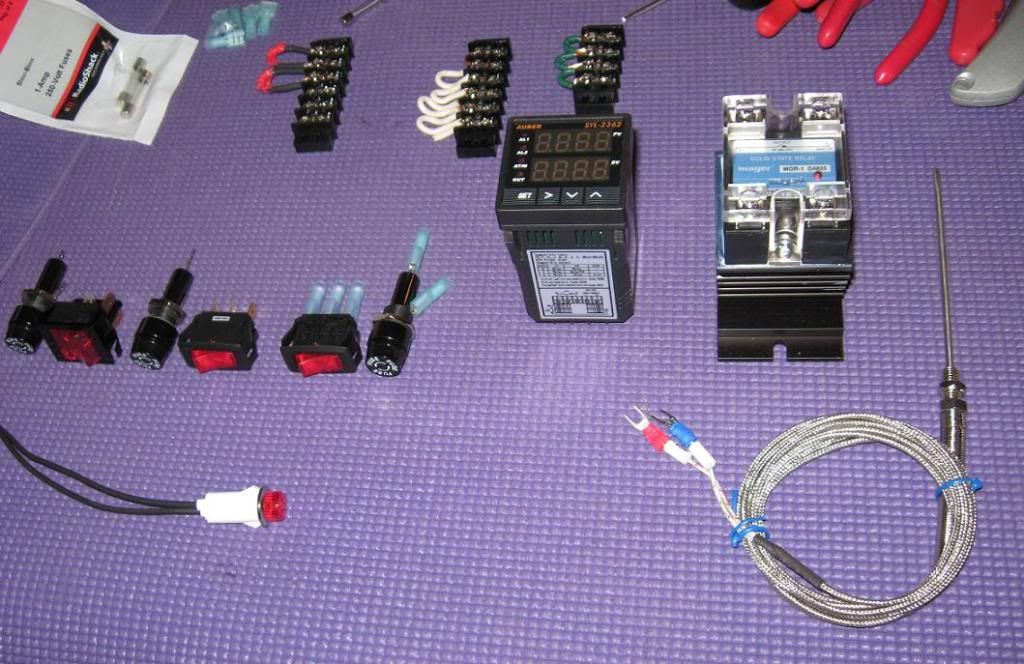
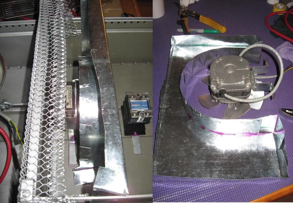
You should use a type K thermocouple with a PID temp. controller. The controller should activate a solid state relay, mounted on a heat sink, to give power to the heaters.

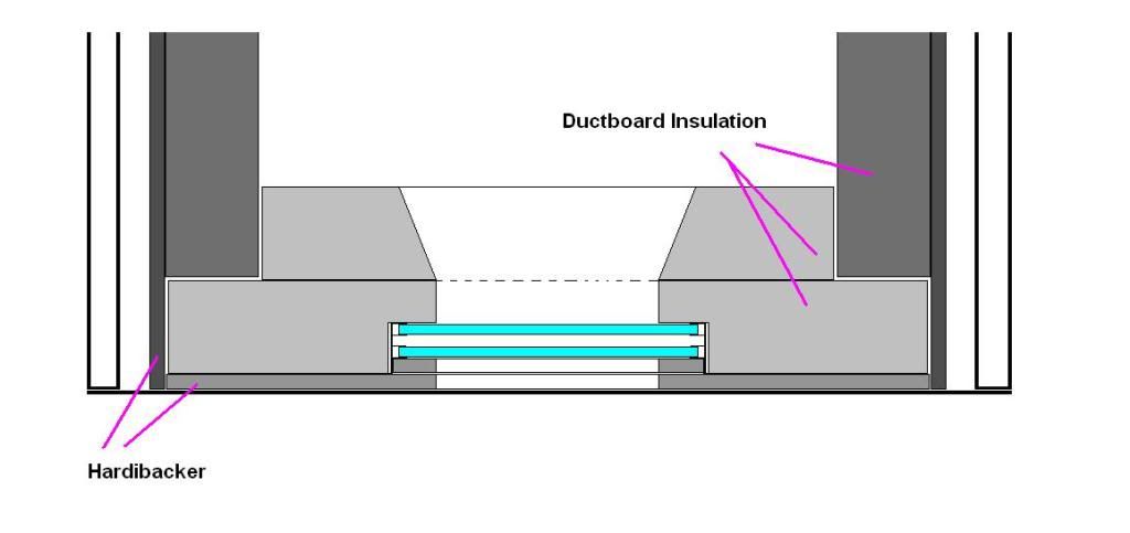
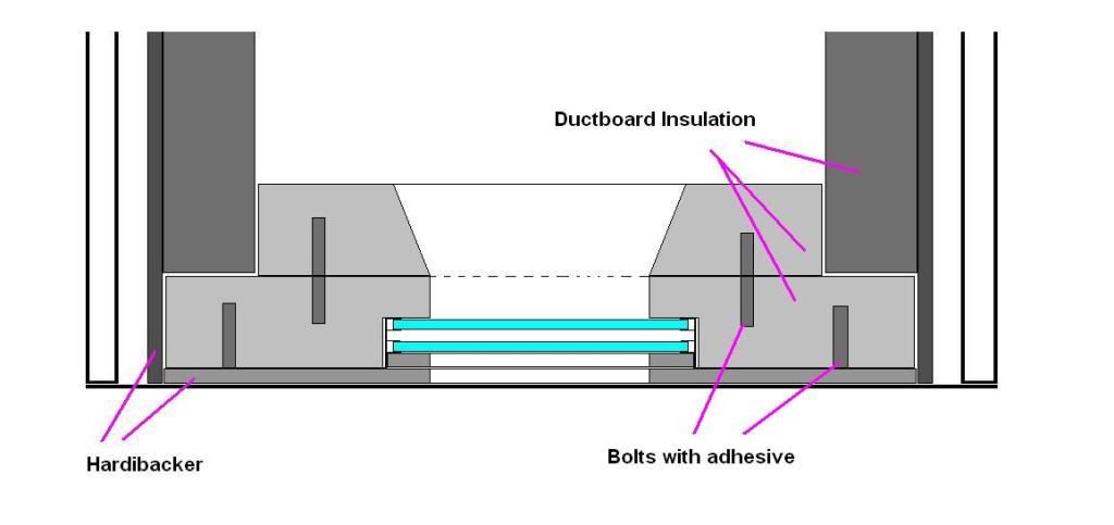
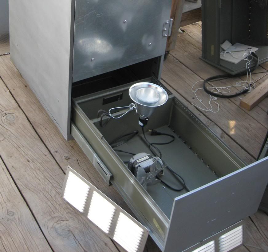
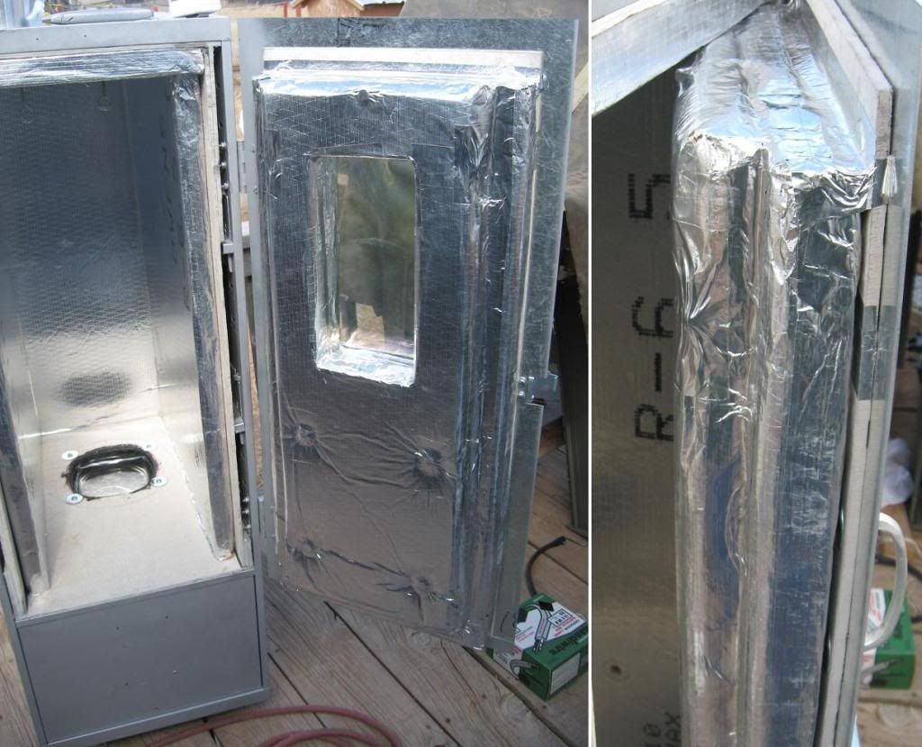
If you insist on putting the controls in the bottom cabinet like you have planned you need a blower to intake fresh air to this area, and this NEEDS to be interlocked (I'll get to this later) to the heater control to kill power if the fan fails. Whether or not this works depends on how well insulated the bottom is.

Probably the best option is to get an external box, either type1 (keeps fingers out, think back of your computer monitor) or type3 (resistant to dust), in either fiberglass or mild steel. Mounting this to the side, or even better using standoffs (i.e. washers between the box and side of oven). Downside of this is you have to buy one and the back panel to go with it. Upside is you only have to buy heater wire (heavy insulated wire) to go to the heater, not the whole circuit. This would also stay cooler so you can use whatever blower you have to circulate the hot air inside the oven. This is probably best because you will have hot and cold pockets without air circulation and you thermocouple would not read accurately.

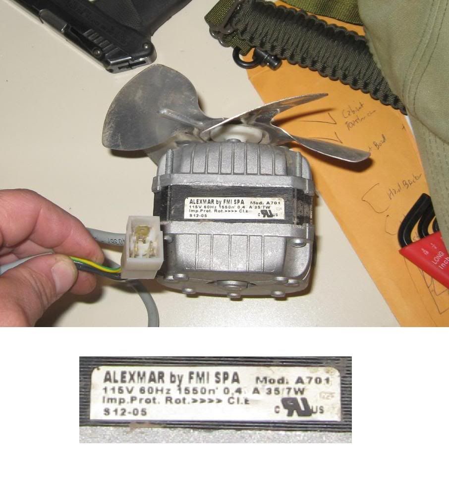
msahlm, based on 1600w load you would be within spec to run off a 15A breaker, but a 20A rated circuit dedicated to the oven would be recommended. Also, the cooling fan, power to the ssr, the light, and power to the pid should all have seperate fuses. 1/4" slow blow fuse holders are 5-10 bucks a piece, the fuses are cheap, and each fuse should be sized for the maximum current draw of the device. The motor should have a label on it, amp draw would be noted by FLA (full load amps) on the motor tag.


Where to get this stuff
---------------------------------------------------------------

The auberins.com website you posted looked reputable there is also automationdirect.com which I know for a fact has some stuff that is good and I would prefer since I know of their stuff. Don't overlook grainger or mcmaster carr either. You can order mcmaster online as an individual and many times the grainger store will let walk-ins order, if you're pretty sure about what to get. Both their catalogs are online.

Also look at home depot and lowes, you can buy wire by the foot at these places since you don't need a whole roll. Go in and ask for something like 12ga heater wire or something with high temp insulation. Reference what they have back to your ugly's book and see if the insulation class will work, if its not in ugly's google it. You could potentially score the fuses, fuse holders, and enclosure at these places too.

Look at industrial electric suppliers (i.e. Elliott Electrical Supply). They typically deal with contractors and industrial customers, but most of the time will sell to walk ins too. Their shops aren't really there to browse around though. Walk up to the counter and say something like I need a PID temp. controller with relay outputs for 110v. You could probably also ask if they had any wire with a fiberglass jacket that would be suitable to run a heater in XXX*F temperatures, something maybe suitable for a kiln. You might ask if they sell it by the foot, they will probably look at you funny or they might sell it to you by the foot.

Make you list of particulars go in and see how much it will cost. A lot of times they have this kind of stuff on the shelf. If you get the cheapest thing they have on the shelf, meaning you don't have to order it, then you will probably be getting what most of the industrial places around the area use. That will be plenty good enough.


What stuff to get
---------------------------------------------------------------

The enclosure. Get more space than you need. Something like this box would do. A Nema 3R rated fiberglass box would be better. You could get it from Elliott for a little over 20 bucks plus the back panel.

Fuse holders. You need one for the light, temp. controller output, heater, and fan.

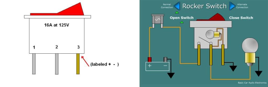
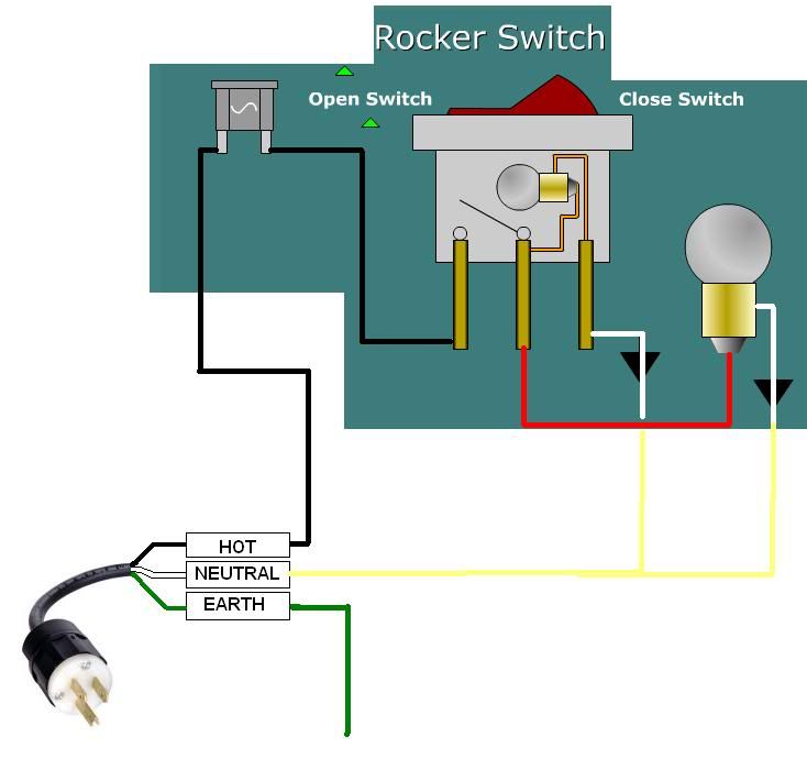
Switches. I would say getting switches with enough load rating to handle the stuff in the system would be the cheapest route on something simple like this. Otherwise you would have to have a bunch of relays at 10-15 dollars a pop plus a 5-10 dollar terminal block to plug them into. Take a look at this switch. I would go from the fuse to the switch to the load. The only thing I wouldn't switch is the line power to the SSR and the power to the temp. controller (but I would switch the power for the outputs to the temp controller, again right after the fuse).

A solid state relay. I use a lot of idec stuff at my work. I couldn't find anything online similar, but the one you picked out looks just like it with the heat sink too. This relay is an alternative. Be sure to oversize this as it will be de-rated as it heats up and the hot air in the garage will affect its rating too. You should be able to get this locally at the industrial electric supply. I like the style you picked. Be sure to look for the ratings of 110-120VAC control power (if the control voltage rating is too high it won't be activated by 110v) and 110-120VAC load rating at least (the higher the better on the load side, although you don't gain anything past 120v).

The PID controller. The one from automation direct looks good. The one you found wasn't bad either. Things to look for are 110-120VAC control power and relay outs. If the outputs are triac or transistor normally they are DC from the controller which of course puts a load on the controller to switch the SSR.

And of course a thermocouple like this. It doesn't have to be just like that. There are ones that have threaded fittings, handy for screwing into the side of a file cabinet. A lot of the stuff on automation direct, like thermocouples, are designed to be used in food grade washdown areas so are more expensive. They are reasonable for what you are buying, but you could probably get this cheaper elsewhere.

Couple of odds and ends would be terminal blocks (make sure you look at the load ratings!!!).
Fuse holders of course. These could be open type or din rail mount or panel mount.
Romex clamps or cord grips to keep from pulling the wires out of the box. And of course wire, but we've been over that already. Just make sure that you size the wire for the load!

For the power input I would probably go to home depot and buy a decent 10ft 14ga extension cord, with grounding terminal!! Cut the female end off strip back the insulation and you have a cord ready to power your box. You could buy the wire and field attachable plug, but this is probably cheaper.


How do you wire this stuff together????
---------------------------------------------------------------

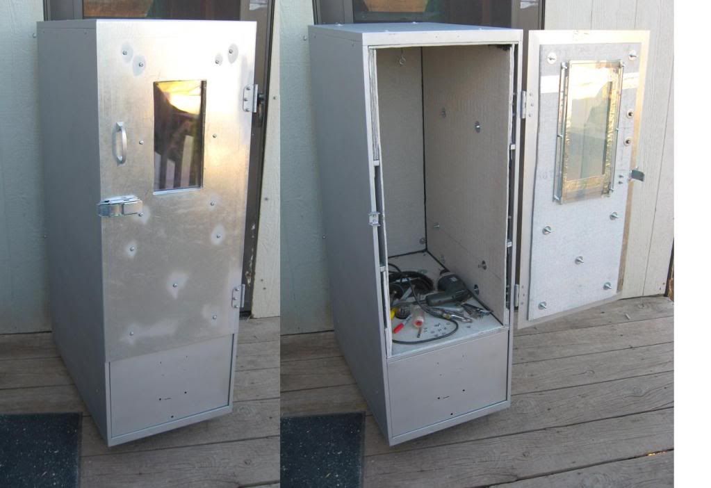
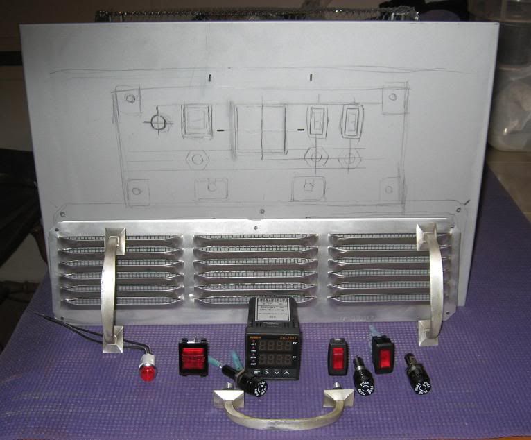
First lay out where you want everything mounted, obviously temp. controller and switches on front. Then cut all holes and mount everything before you even pull the first wire. Drill the holes for mounting the box during this stage.


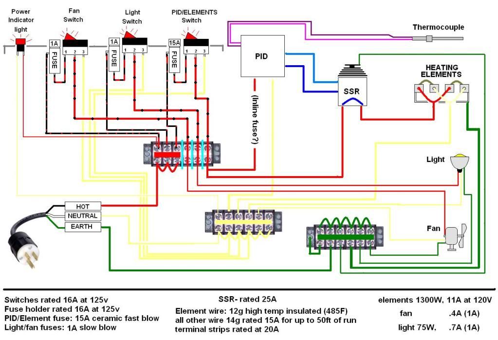
Well like I said come into the box with the cut-off end of your extension cord and terminate all three wires on the terminal block of your choosing. Most importantly take a wire from the ground this this terminal block, but a crimp connector on it, and put it under a bolt attached to the box. Likewise anything that has a ground terminal, like a temperature controller or blower motor or light, need to have their grounding wires attached to this same point.

Run a wire from the hot in, typically black, to the first fuse block. The fuse blocks should all be mounted together. This wire should be the same size as the incoming power wire. Make small jumper wires and go from the top side of each to the one next to it. Now you have power to all your fuses.


__________HOT WIRE________
_|_ _|_ _|_ _|_ _|_
|F | | | | | | | | |
|U | | | | | | | | |
|S | | | | | | | | |
|E | | | | | | | | |
|__| |__| |__| |__| |__|

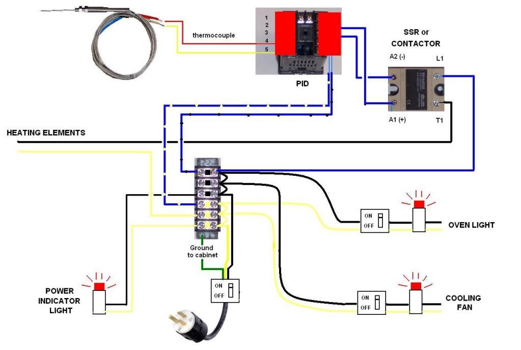
Come from the first fuse to the 120VAC L1 terminal of the temperature controller. Then come from the L2 or N terminal back to the next open spot on the terminal block.

Now come from the second fuse to the to your first switch. From the other side of the switch to relay common for output 1 on the temperature controller. Then another wire from the relay output to the A1 terminal of the ssr. Then from the A2 terminal of the SSR back to the next open spot on the terminal block. This switch will allow you turn off the heater even though the controller is calling for heat, allowing you to monitor the temp. of the oven. If you unplug, or plug the unit with the heater try to go it will probably trip the breaker.

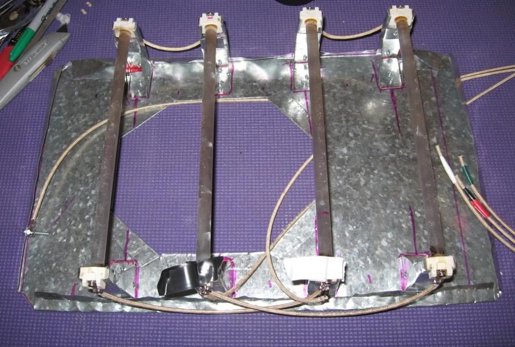
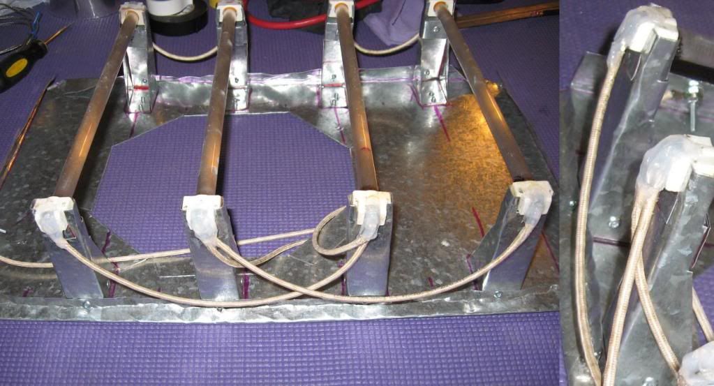
From the third fuse run a wire to the L1 terminal of the SSR. The another from the L2 or N of the SSR to the heater, this would be done with you heater wire or fiberglass wrapped wire or whatever you decide is suitable for the load and temperatures (OBVIOUSLY MEANING PICK A WIRE THAT IS INSULATED AS SUCH THAT IT WON'T CAUSE A FIRE). From the other side of the heater come back to the next open terminal on the terminal strip, still using heater wire at this point.

Now come from the second to last fuse with a wire to the second switch. From the other side of the switch go the the positive terminal of the fan. Then from the negative (neutral) back to the next open terminal on the strip. Can you see where we're going with this? With the light the same way.

Now to tie the neutrals together. Just like we ran the positives go from one neutral terminal to another with short jumper wires, then bring one back to the neutral of the incoming power, typically white.

Almost there.
Check all connections. Make sure that you can follow the L1 or "hot" wire power flow. It should go from one point to the next basically going through one or more switches then to the "load" and from the load directly back to the terminal strip to terminate at the neutral.

Now make sure again that you have the properly sized fuses based upon the maximum rated amps for the equipment you are using. This does not mean rated amps plus half an amp, it means the rated amps! If something keeps blowing the fuse try to troubleshoot it or pm me and I will help if I can.

Last but not least check grounding again! (See how much fuss I made about this!!) Make sure everything with a metal case or ground terminal comes back to the common ground.

FUN Time
---------------------------------------------------------------
Turn all the switches to the off position and plug the thing in. Get the book for the PID controller and set it up. You are going to be using a thermocouple, not rtd, so there is one thing to make sure of. The thermocouple will probably be for 4-20mA signal so you will have to set this in the controller. And there will be some other things to set. Every brand does it differently. If you have questions pm me.

Once you are sure that everything is programed right unplug the thing. Install the thermocouple on the signal input terminals.

Okay. Plug it back in and flip the heater control switch. The light on the SSR should come on. It will probably take a little while to get heat from the heating elements and a couple of minutes to actually raise the temp. in the oven. Once that is gtg then flip the switch back off.

Now test the switch on the fan and light. If everything is good do a test run. Bring the oven up to temp for a prolonged period while babysitting it. This would be a good point to calibrate the temp sensor and run the auto-tune feature if it came equipped. If you smell burnt plastic or anything really unusual shut it down and find out where it is coming from.

If you have questions feel free to post back here.

Caveats
---------------------------------------------------------------

Thermocouples are meant to be hooked up one way. Don't worry if you hook it up backwards. The temperature on your controller will probably just start out high and count down.

Always ensure good grounding.

Jumping from one terminal to the next is an electrician no no, but not necessarily a violation of NEC. The wire has to be rated high enough for the cumulative load of the entire circuit. But say you determined 14ga would be good enough for your input power then if you use 14ga throughout the system you should be good as long as the terminals are rated for wire that big.

Be safe, do research, double check, and ask questions if you are unsure. And it never pays to skimp out and buy small wire with cheap insulation. Upsize if your terminals can accommodate it.
 
Re: homemade paint oven (more pics added)

Here's just a few shots of what we'd done here:

The separate 'control-box'
CerakoteOvenBuild008.jpg


Here's one shot of the inside of said 'control-box', during construction.
Tools007.jpg


And here's a shot of the elements inside, "flat-out-give'n'er" as a meltdown test.
CerakoteOvenBuild018.jpg


There are many ways of doing things, and this is working for what we want it to do, here. That being said, the advice and guidance that TxAg08 has put up here is fantastic, and addressing so many of the issues to which I'd alluded to. I'm sure now it is seen clearly.

Largest thing being, that I know what I don't know, and I refrain from speaking about that which I don't know.
 
Re: homemade paint oven (more pics added)

Thanks Sean. I hope everyone finds it useful. Didn't realize that it would take so long to write and post. This is a pretty simple project that seems a little daunting if you don't know the basics of things. That's mainly what I'm trying to get across.

I really like your oven Sean. Just the right size. It is probably hard to get everything to fit sometimes but with the size and burner arrangement I imagine you get very consistent burner arrangement without the use of a fan. Do you just hang barrels with a piece of wire looped through? Do you still have it plugged at this point?
 
Re: homemade paint oven (more pics added)

Well I started my oven project today...so far $22.00 I bought a 19x19x52 peice of ducting from a friend that has a heating cooling company. he had it left over from a job he threw in a cap and the fittings to hold it all together. I found a electric griddle at a thrift store, it looks new but a leg was broken off so it wouldnt sit flat It has a controller that goes to 400deg. best part I was looking at the hardware store and couldnt find anything, so I am leaving and spot a dumpster, there is a 19X30 square frame with 4 new rollers sticking out...SNAG ..Ill post up some pics soon
 
Re: homemade paint oven (more pics added)

TxAg, Thanks alot- helps me immensely. I've read through your posts a couple of times and will probably have to read and dissect it several more times to get my mind around some of the unfamiliar material.

I will be sending you a PM about some of the specific stuff relative to my build to spare everyone else following this thread from information overload.

-> Just so you know, i do get the importance of grounding everything to a common ground and giving that ground an avenue back out of the oven (through the 3rd prong of my power cord)

-> I do get that each electrical component needs it's own fuse appropriate to blow when that item draws more amp than it should in normal function. I hadn't thought of making a fuse block- back to the drawing board.

-> I do get that using the appropriate size wire and connectors is critical, and that the wire needed is different at different temperatures.

-> I do get what you are saying about having my cooling fan tied in directly with my heating elements so that if the fan fails, the heating elements will not continue to heat- but I'm not as concerned about the cooling fan being so "real-time" critical to keeping my electronics at a safe temperature.

I think my plan of having the electric components in the bottom drawer of my "filing cabinet" is going to be a little more of a "seperate" box situation that you might be perceiving. Think of it as a seperate semi-removable box within the cabinet that will have it's own high volume circulation fan drawing ambient air- I've gone to great lengths to design the oven NOT to transfer heat from within the oven to the outside shell- and I intend to ground truth that intensly. If the oven produces more heat inside the lower box than anticipated- The plan involves being able to pull the entire (fully enclosed) control box out of the oven cabinet (it's built in a drawer) and leave it out during a bake. I have purchased plenty of high temperature wire (it's 12 guage fiberglass insulated rated at 250C (485F)- sound OK?) to create an unbilicus long enough to enable me to pull the drawer in and out. Maybe I could simply have a (home style) thermostat inside the control box that cuts all power if it hits 130F?

When I started this project, I had found many oven builds where guys had simply used a dimmer switch or oven thermostat to control the temperature- I want to do this as safely and as properly as possible, but within the sideboards of what I can afford. I'm confident I can make it as safe or safer than the original toaster oven (which didn't even have a 3 prong grounding cord- and didn't have a single piece of wire in it bigger than 18 guage) The Auber components I posted are at the top end of what I'm going to spend on this- although you sold me on the SSR/heatsink over the contactor.

Thanks again for your help- I'll try to pull together my new improved wiring diagram (plan) and all my questions and PM you with them all at once so that I don't turn into a long term PITA. I've got the ugly book on order, what's the difference between the 2008 and the 2011 book?

Any help on this fan- It's made in Italy, salvaged from a small commercial glass display refridgerator (the ones that keep sodas cold in the checkout isle at the store)Watts/Amps? What size fuse?

buildpic18.jpg
 
Re: homemade paint oven (more pics added)

<div class="ubbcode-block"><div class="ubbcode-header">Originally Posted By: KNIGHT11B4</div><div class="ubbcode-body">

No guy, not you, the person who i quoted in my post...

He has padded his post count with crap and he has now been banned.

Nice oven. </div></div>

Sorry Man- I could not make the connection- I don't spend a lot of time on forums outside of this oven project. IGI- It takes a certain post count to sell stuff on here- I'm just padding my posts because post count = intelligence, know-how, and respect
smile.gif
 
Re: homemade paint oven (more pics added)

Thanks for sharing that oven idea. I liked the flat black you did with the 80 grit, no reflections coming off that one for sure.
 
Re: homemade paint oven (more pics added)

msahlm, I wasn't trying to refer to you directly. I realize I made some sarcastic comments in my posts, but I did not mean anything by them they were for entertainment only. I realize going through this stuff can get dull.

Please realize that I don't know the scope of your skill set when it comes to electricity and I also needed to think about how people would use this information at a later date. I would hate to find out down the road that someone hurt themselves because I gave them just enough information to be dangerous 2 or 3 years after I posted the original information.

Regarding your motor.
Google search reveals that alexmar is an italian manufacturer. This means they use commas instead of decimals in numbers. That motor will draw 0.4 amps by my reading the label. I can only assume that 1550n' refers to 1550 rpm. Should work great assuming it works still. Making a shroud will help it move a lot more air, some cheap tin exhaust vent from the HD should do the trick.

Sounds like you're on track with the wire. I didn't mean that you had to use a fuse holder like I linked to. If you can find a little open type that takes an inexpensive fuse and is easy to fasten 12ga wire to then use it! I was just trying to provide one avenue in case you didn't know which direction to go.

Looks like a nice oven though! I might have to send my tikka out to you so that you can match it to the new Whiskey 3 chassis.
 
Re: homemade paint oven (more pics added)

Tag.
 
Re: homemade paint oven (more pics added)

<div class="ubbcode-block"><div class="ubbcode-header">Originally Posted By: TxAg08</div><div class="ubbcode-body">msahlm, I wasn't trying to refer to you directly. I realize I made some sarcastic comments in my posts, but I did not mean anything by them they were for entertainment only. </div></div>

It's not hard to read the wrong tone into what's written in these posts- So for the record, don't read anything into MY tone except for gratitude, a genuine curiosity, and excitement over (kinda) learning a new skill set while creating my own tool that will provide me good service for some time.

It is basically impossible for a professional (like TxAg08) to give advice on how best to do something "kinda" right. It's like a professional sky diver explaining how one might be able to build a homemade parachute that will PROBABLY keep you from becoming a jello splat. No one should have absolute confidence in guidance (they think) they've gotten over the internet, nor build electrical devices without the direct consultation of a professional electrician who has hands-on knowledge of the constructed device. I've purchased the Ugly book and will consult it, received sound advice from professionals, and have researched to obtain a clear understanding of the forces at work. I plan on doing the work myself, but I won't be plugging the thing in until I get a local certified electrician to give me the all clear. Nor do I plan on ever operating the oven without directly monitoring the ovens components and temperatures while it fires. I suggest the same for anyone else with plans to build an electric oven.
 
Re: homemade paint oven (more pics added)

This thread may have jumped the shark a bit with all the technical vortex and disclaimers.. Let's get it back on track for the window shoppers- Here's my take on how one might mount heating elements from scratch.


The other toaster oven I picked up would have been much easer to use as the ceramic ends of the heating elements were more user friendly to create a mount for (that oven was a 1100W and only had two elements- so I went with the bigger one). With these elements I had to bite the bullet and just make sheet metal pedastals for each end of each element from scratch. (8 total)

I made a paper templet and traced it onto the galvonized sheet- then cut, then folded, then pop rivets- sturdy enough and very tweekable to get just the right fit and hold.

buildpic19.jpg


pop rivets hold it all together, floor plate with hole for my undermount oven light (which we all agree is a ridiculously unnecessary feature)

buildpic20.jpg


With the element pan in place, I experimented a bit on a shield using some of the cheap-light expanded metal used for stucko- this is attached to the side mounted eyebolts I had put in for this purpose- this is very much a first draft- but you get the point- There will be a shield over the heating elements.

buildpic21.jpg


buildpic22.jpg
 
Re: homemade paint oven (more pics added)

Very Nice!

Looks like it is coming along nicely. I like how you did the mounts on the elements. Do you stick them in the vise and break them or use a wood block?

Don't know if they expanded metal will stop a barrel falling but should catch anything else. Don't know how you would do anything else, like a drip pan, since the light it already installed. This should work out though.
 
Re: homemade paint oven (more pics added)

Thanks TxAg. I used pretty light guage steel and was able to break and bend them using my fingers and pliers- I did use a pair of welding vise-grips with a long gripping face that basically functioned like a vise would, but it really wasn't necessary, and I learned early that the element mounts were not going to end up being all that pretty to look at so I quite worrying if the bend breaks looked sharp or not.

As far as the element shield- you are right, the shield pictured is just short of being adequate if a rifle fell on it. I'll plan a simple rectangular frame (with the light expanded metal spanning it) and it should end up working perfect.

I had not planned on any sort of drip pan as I did not think about any sort of dripping liquid. I get that there will be the possibility of oil drips (like in M1K3's OP) but I'd assume that would be pretty minimal, The heating elements are designed to hold up to a 400F exploding burrito (and had at one point from the looks of the original toaster oven), and should be fine. I hope I'm right, but I could always retrofit some kind of pan without too much issue.


By way of update for the interested.....


The door insulation is finished, and fits very snug. Looks like it seals well on several planes and I hope it equates to very little heat making out to the door- It's so snug that there is a bit of a visual gap when the door is closed(unless I put my shoulder into it), but I'd rather have the insulation seal than have the metal seal up pretty- so I'm not messing with it.
buildpic23.jpg


I mounted the light- tried to keep it simple- the drawer had a movable partition and I just set it to where the light would line up with the portal with the eyebolt I had.
buildpic24.jpg


the drawers all have adjustable file hanging rack which were very stout (they just do not make things like they used to) I adjusted one to fill in front of the drawer partition, and then cut off the excess steel runners. The drawers also had a double wall in the front panel, and I used the inner panel that I removed from this door as a top lid for my electric components box- It's got to be sealed so that you can't get your hand (or a mouse) in there to short the exposed wires on the future wiring terminals (i.e- electrocute yourself). Simply cut flashing for the side walls.

buildpic25.jpg


The plan is to cut vent hole in the back of the bottom drawer, a vent hole in the front panel-covered with this vent register (see below) and duct the fan within the electrical box (see above) to pull fresh ambient air from the back and out the front-
buildpic26.jpg


I had initially planned to duct the fan in the back (intake) My thought was that the front vent would be the only way out of the sealed oven shell and that it might keep a slightly positive air pressure withing the shell of the oven and help to circulate air within the dead airspaces around the oven. I ditched that dumb idea- I don't need a cooler for the oven (duh)- just a cooler for my electronics and I want to make sure (cool) air is flowing over them.

buildpic27.jpg


....and this way If I find that the electric component box stays/gets too warm during baking (over around 130-140F), I can just pull the drawer out when I fire the oven and the fan will still function to keep air flowing over my SSR.

(yes, I'd have to figure out a new way to mount my ridiculously unnecessary light)

buildpic28.jpg


all the electric will be common grounded to the drawer, but also to the cabinet.

Note to builders- My $100, slash $200, slash $300 oven is looking to finish up at around a $350+ oven. I knew it was happening and chose to take it that way, but I will say that a good old 4-drawer filing cabinet could be used in a similar fashion to what MiK3 did in the original post and be done cheaper than either of us where able to do. It's a perfect size/shape for gun work and a great size and weight for a 120v shop tool- moreso with some harbour freight wheels on it to move it around with.

 
Re: homemade paint oven (more pics added)

Sorry to beat on a dead horse over all this electric stuff- but I've got my innerds on order and am about to embark on finishing up my oven.

I was hoping TxAg or others could look over my wiring plan and see if they notice any GCE's (gross conceptual errors).

I've gotten some local pro-electrical advice and am told this should be a lifetime tool when I get her done.

The exception is the fancy superfast fuse that's recomended for use with an SSR- What i'm told is that if a power surge ever takes out my SSR, buy another $14 SSR replacement and get back in the fight- sounds like a winner to me.

(pic of wiring diagram removed- found some mistakes and a better diagram follows later in this thread)
 
Re: homemade paint oven (more pics added)

Msahlm,

Seeing as my list of credentials are:

Interweb'ly certified electrical engineer (with a rocking topstrap)
Professional Theoreticist with a background in hypotheticalism (suppa came late'a)
Regional Official electro-metallical fizzicyst (previously: sparking and popping with some "smoke-releasing")

Now that above said qualifications are established, I can most definitely say that your schematic of your proposed project is indeed colorful and quite blocky in it's 'Post-Modernistic Pre Blue-Period' rendition.

Makes one generally think that it might work...
 
Re: homemade paint oven (more pics added)

In my shortest post in this thread:

Looks good! Slow blow for the PID wouldn't hurt. Post pictures when you get everything laid out and running!
 
Re: homemade paint oven (more pics added)

<div class="ubbcode-block"><div class="ubbcode-header">Originally Posted By: Sean the Nailer</div><div class="ubbcode-body">

Now that above said qualifications are established, I can most definitely say that your schematic of your proposed project is indeed colorful and quite blocky in it's 'Post-Modernistic Pre Blue-Period' rendition.

Makes one generally think that it might work... </div></div>

Yeah, you should have seen my original version using colored pencils on paper- looked like Jackson Pollock's take on a rainbow Medusa- I do tend to get over the top- but diagraming this has helped my understanding

For TxAg, the guy at Auber told me that the PID only draws like milla-amps- should I just go with a 1A slow blow, or some lower amp fuse closer to the PID's actual draw? I'm assuming there will be a earth ground post on the back of the PID somewhere- that's not shown in my diagram but I'll ground it as well since it has a plastic housing and may not ground to the cabinet. Also I noticed my diagram left out the most important part of the (green Earth) ground loop- bolting it directly to the cabinet and the drawer.

I hate to do it to the 5,000 other people who have looked at this "Gun-forum" thread (and could care less about wire spagetti or my long winded ramblings)- but I have one more electric question I cannot find an answer to in the Ugly book or on the interweb.

My illuminated rocker switches seemed pretty simple but did not come with a diagram. The general consensus on these three prong rockers is that 1=supply (lectric in), 2= load (lectric out) and 3= earth ground for the internal light bulb.

My worry is that the #3 prong is a gold color and is labeled (+ -). Any help here? Does that track? should it be instead 3=supply, 2=load, 1=ground?


rockerswitch1.jpg


Thanks everyone, the good news is I'm almost done asking gun builders for electric advice.
 
Re: homemade paint oven (more pics added)

Seems like I may have found a GCE on my own: I had switches grounded to green as per instructions- but I think that's related to a 12V system- seems like they will have to wire back to the neutral in a 120V system and not just to ground (the way a 12v system would work) something like this, correct?

ovenwiringdiagram-b.jpg


That actually makes more sense relative to my previous post about the rocker switches- But I still have the question would it be 1=supply,2=load,3=neutral, or 3=supply,2=load,1=nuetral

rockerswitch2.jpg


Re: homemade paint oven (more pics added)

What do you guys think about this idea? I cannibalized a harbor freight heat gun and installed it in the bottom of mine. The box seen on the outside is just a transfer box, I didnt want to be blowing in outside air, so it is sucking air from within the oven. I think it should supplement the toaster oven coils quite well as Im not sure the two coils I got will be enough for 350 degrees.

Once I get all the insulation installed and the toaster oven coils in place, I plan on using a sheet of aluminum on the lower right side of the oven and having a nice radius on that corner so air will want to flow in a circle around the cabinet.

Any comments or criticism on this idea?

oven1.jpg

oven2.jpg

oven3.jpg
 
Re: homemade paint oven (more pics added)

msalhm,

I'm not sure what to tell you. As a typical convention in the USA on 120v circuits the gold contact is almost always reserved for L1 (120v Hot). Yes you are going to need to wire the other side of the lighted switch to the neutral not ground. I have a very good explanation as to why, but it is quite long winded.

My advice would be to get a multi-meter. A $5 one from harbor freight would be sufficient, although I use this one daily and a couple of others for more specialized troubleshooting. Put the meter on ohms (a.k.a. check continuity) and measure the ohms between each pin. You should be able to figure out which one is the hot in, the light, and the load contact.

Jonaddis84,

Be extremely careful. The type of heater you have has insulation on it and is designed to have air flowing over it. It is not designed like a toaster oven in that it can sit for a long time radiating heat without damaging itself. You could easily burn the wire in two, and/or cause a fire. On the other side of the coin I work with this type of heater every day, albeit in a larger form. Put the thing in a metal, grounded, tube and put a fan on one end and you now have a convection oven! And your wife wanted to run out and buy that $1200 GE model. Imagine her surprise when you give this to her for her birthday!

edit
------
My bad jonaddis! Didn't see how you had it installed. That looks potentially safe. Just keep an eye on the oven temps!
 
Re: homemade paint oven (more pics added)

Jonaddis, I think what TxAg said still may be valid for your plan since it is sucking (HOT) air from inside the oven. But it's possible the heat-gun-guts can handle 300-350 inside there. Your blower motor is what I'm worried about and my guess is it's pretty crucial that you've got cool air blowing across it to keep it from melting down- You might think about making a duct (sucking)from top (blowing)to bottom. Cool idea, worth a shot, make sure it's grounded.

I bet your elements will do fine- I think it's just a matter of HOW FAST your oven gets up to temperature- I'm in the same boat to find out here pretty quick.
 
Re: homemade paint oven (more pics added)

You are doing a nice job but I think you are going much farther than needed. Circulating the air slightly in an effort to keep the heat even is good but not nessesary. I have cooked a lot of Cerakote and air circulation is not a factor. The heat is what aids the catalyst in hardening the finish. With the heating elements in the bottom there is going to be a lot of natural air movement from the rising hot air and the cooler air falling. A stout wind from a large fan or blower could cause your paints to run and will surely blow dust into your finishes if any is ever present which it always is due to deterioration of the insulation over time plus just normal air contamination that is always around us. Cerakote cures at 250 to 300 degrees. I doubt the heat gun is going to be needed as 1500 watts worth of heating elements will surely have the capacity to drive your oven up to over 450 degrees even with minimal insulation. I too have comcerns that the heat gun is designed to draw cool air and drawing hot air most likely will lead to early failure. That failure will also blow dust and smoke all over your project.

I am building a tall oven too at the moment and am looking forward to putting up a couple pictures when it is completed and tested. Mine is no where near as nice as any of these in this thread but I only have about $80 in the whole thing.
 
Re: homemade paint oven (more pics added)

I ran into a wall today, sortof. My toaster oven coils only got me to 170 degrees. I got the $18 oven from walmart, and it only has 2 coils in it. Im also wondering if the plug I installed isnt too long and is not supplying sufficient amperage. With the heat gun running I can get it to around 200-225.

I tore apart the hot plate I used on my old barrel oven, and will install that tomorrow, that beech gets real hot, so hopefully that will get me to 350.

How long are your guys' taking to get to the desired temp?

BTW. I insulated today, covered the entire inside with 3/4" foil backed rigid fiberglass duct board. Then covered that with 1/2" dryrock cement board. Fire seal caulked all the seams. Put some 3" glass insulation in the door. With the oven at 200 degrees the only parts of the outer shell that got hot whatsoever were where the hinges are, and where the oven controls are (since I couldnt get insulation in those parts.)

I think Im going to put some fireplace door seal around the door, I did feel a slight amount of heat coming through the outside of the door.

I dont plan on running the heat gun non stop, my hope is that it will help speed up the warming up process, and also distribute the heat more evenly. Then once its to temp I can shut it down. If it burns out, oh well, it was only $9.99 and old, needed a new one anyway.
 
Re: homemade paint oven (more pics added)

Jonaddis- first question, did you already have the insulation in the oven when it would only hit 170? I know that it would be awefully hard ot hit 300-400 without some thorough insulation.

Also- my only point of advice is to make sure and have your heating controls well insulated or I'd move them out of ther box entirely as I think that could be an issue.

I have not fired my oven yet- but I'm hoping to get to it by this weekend.

Keeping with my over-thorough step-by-step

I got my parts in from Auber and have been collecting all the other odds and ends I'm going to need..
buildpic30.jpg


I wired up my heating elements with high temp wire.. I put black and white electric tape on for the photos to show which is hot and which is neutral- but I don't think it matters which is which. I wired them the same way they had been wired in the original oven- that is two seperate loops of two elements. I also grounded the entire pan which will ground back out to my third prong.

buildpic29.jpg


I wanted to make sure and show that I covered the exposed wire connectors with high temp silicone as they are dangerously close to touching the foil-lined insulation in my oven (design flaw) and that could be catostropic. The silicone gives me a little peace of mind.

buildpic31.jpg


I made a quick ducting shroud for my circ fan- should work great and I'll have to put some holes in it to run my wireing away from where the fan blad will be turning.
buildpic32.jpg


Laying out my control panel- gonna be a pain in the rear- cutting all those little square holes exactly the right size so that every thing pops in and stays in solid. I'm using the old drawer handles from the cabinet drawers to make bumpers to protect my front panel.

buildpic33.jpg


Anyway- I'm almost done and will be as happy as you all to see oven builds other than mine on here- I get that I have kinda monopolozed the thread and I appologize to those who aren't benefitting from my build pics.
 
Re: homemade paint oven (more pics added)

Jonaddis, our oven here takes about 7-9 minutes from cold, to be pretty much 'evened out'. Won't deny that after the first 20 or so minutes, there are a lot less 'cycles' and a fair bit more 'soaking'.

It's all good.