• Watch Out for Scammers!

    We've now added a color code for all accounts. Orange accounts are new members, Blue are full members, and Green are Supporters. If you get a message about a sale from an orange account, make sure you pay attention before sending any money!

Gunsmithing Little DBM install action

LRI

Lance Criminal
Full Member
Minuteman
  • Mar 14, 2010
    6,314
    7,416
    52
    Sturgis, S. Dakota
    www.longriflesinc.com
    We do a PILE of these. It's probably the single most popular upgrade on an existing rifle stock. Fortunately, the procedure is pretty straight forward and one we've become very comfortable with.

    Goes like this.


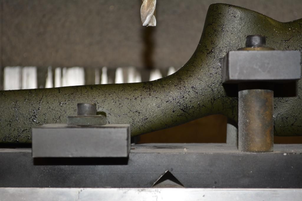
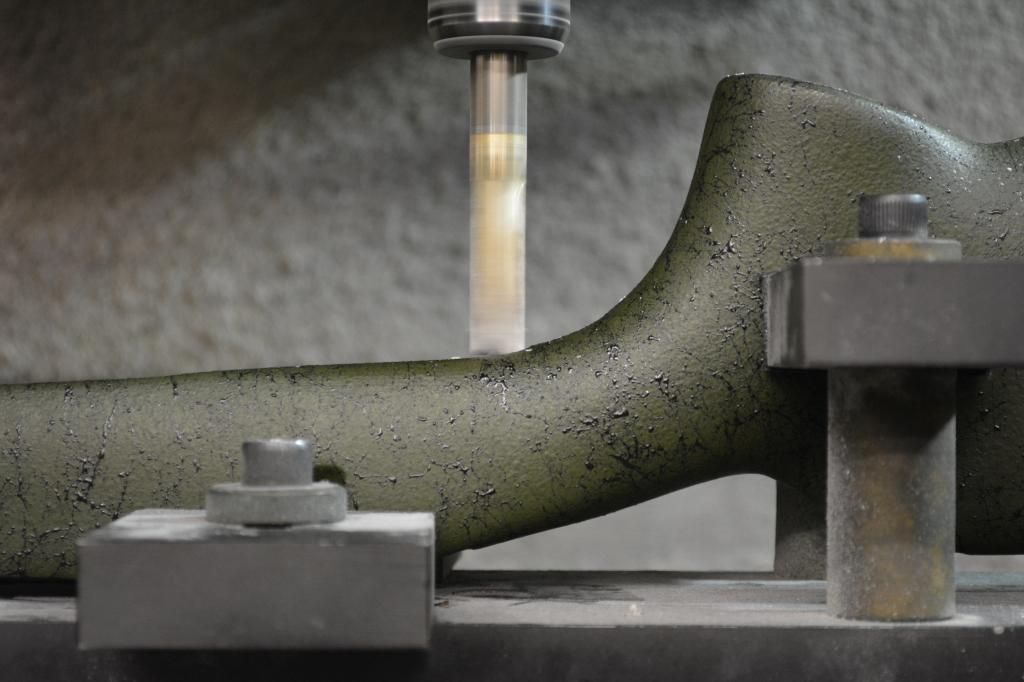
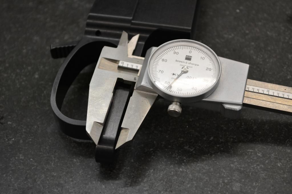
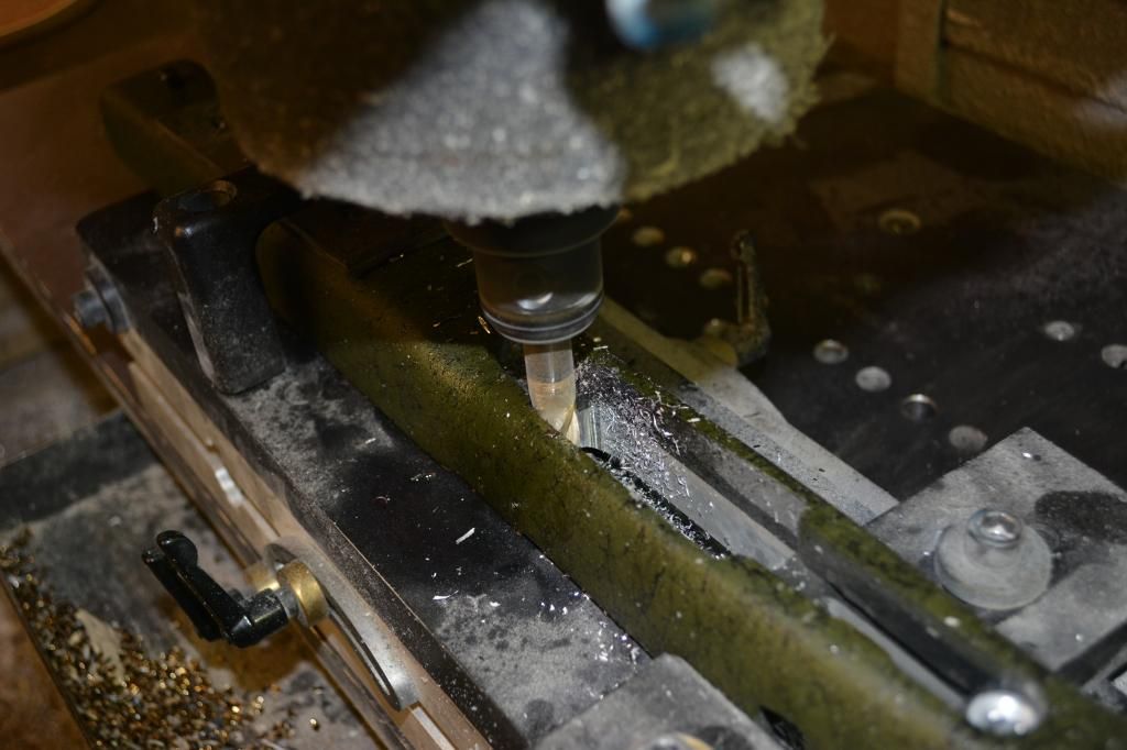
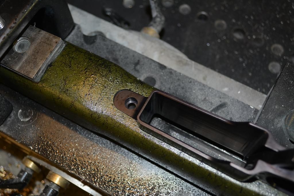
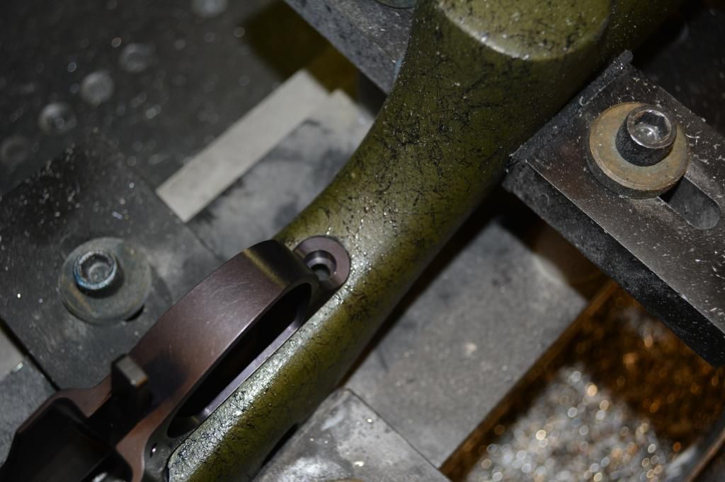
    Step one: Qualify the holes in the stock where the screws go. I ream these to 5/16" as my alignment pins are this size. The pins register the stock in the fixture to get it close. Stocks can vary a bit so its rarely a drop in and go type setup. I have to orient the computer program to the position of the stock in the fixture. Easy enough to do.

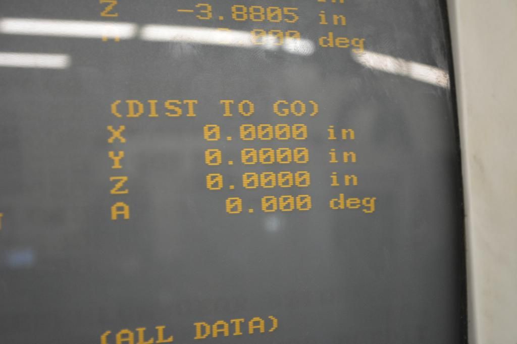
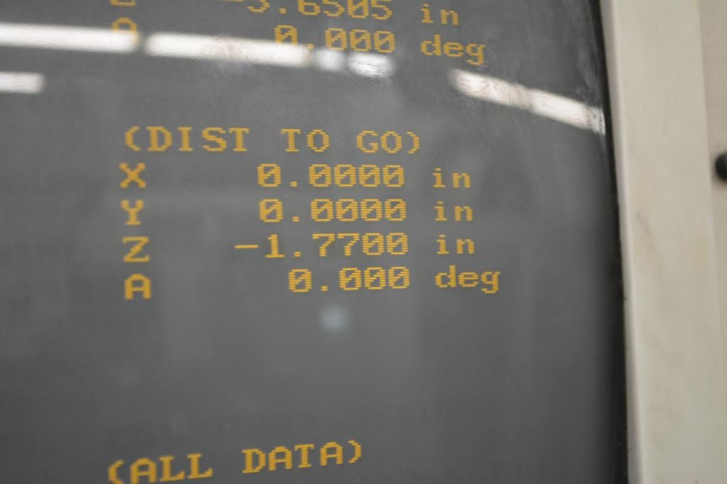
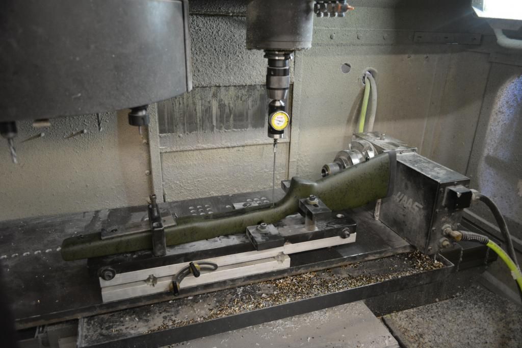
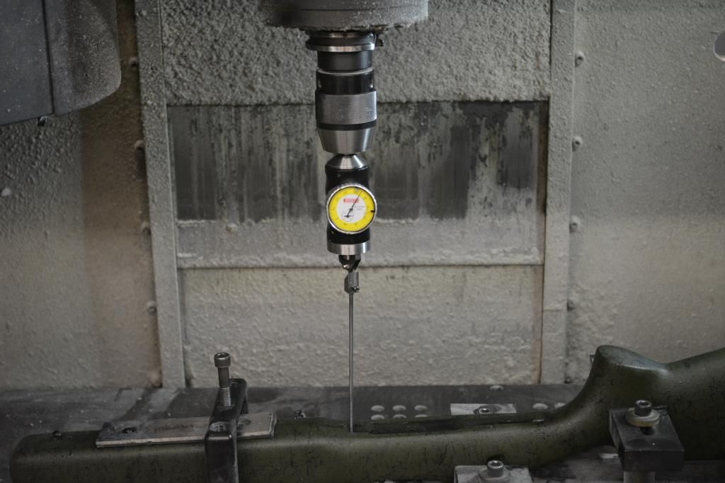
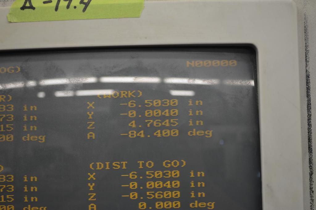
    Here's a coaxial indicator showing position on the two holes. We seat the rear to zero for X/Y and move to the front. S/A M700 type receivers are generally around 6.5" center to center on the spacing. So we rapid over to that distance and check the front. In this case it was 6.503" in X and -.004" in Y. Pretty close, but we'll adjust the program to get it spot on.


    DSC_0001-1.jpg


    DSC_0006.jpg


    DSC_0007-1.jpg
     
    Here's the graphics view of what we'll be doing. Spaghetti...

    DSC_0008-1.jpg


    This is what I consider the "real work". Drawing it up is fairly straight forward. You just reverse engineer the part and create its mirror image. The challenge becomes with tool path strategies. H/S and B/C stocks present some unique challenges because of the alloy bedding block. Your machining two very dissimilar materials simultaneously. Your also using long reach, small diameter tools. The 3F coated 1/4" EM I'm using cost around $60 bucks a piece. They tolerate almost zero side loading. 3 flute tools meant for AL have deep chip gullets and that reduces the base circle of the tool. -Meaning it has little spine to it. The learning curve can be quite steep and expensive if your not careful.

    When approaching corner features your increasing the tool contact with the part as you enter that feature. Loads applied to the tool increase significantly. This is what snaps small endmills. The shock loading of it suddenly engaging 90 or more degrees worth of material causes the tool to "wrap up" like a drive shaft on a dragster. Carbide doesn't tolerate torsional loading very well. "Dink" is often a very expensive sound in a machine shop... :)

    DSC_0009.jpg


    Were at a significant disadvantage here because were cutting this stuff dry. I can't use flood coolant on a rifle stock. That would just be a mess.

    So, we get creative in how we attack this bugger.
     
    Last edited:
    I wish I lived in Sturgis I would be that guy sweeping your floor that your trying to kick out the door.
     
    The assumption is often made that actions reside in stocks on their "showline". Basically meaning "half in, half out". Unfortunately this is not always the case. Installed heights vary-sometimes significantly. If it were standardized, it would be a snap to fit these up as the height above the fixture would never change. I program all this stuff so that the showline edge of the stock is the Z axis zero point. Meaning everything is done in a positive Z value. (which is unique cause usually the tallest feature is the Z zero and you work in a negative direction (down).

    For this its better for me to do the opposite though.


    So, we allow the program to run its first segment. Once the tool goes as low as its going to, I stop and determine how far above the stock it is. Then we adjust the entire work coordinate system and bring the plane down to where the stock actually is for this particular run. Adds a few seconds, but avoids collisions and replacing customer's property!
     
    Were done. Now to check the fit and the installed height. The front pillar on the Stealth is .725" in length. So, the saddle (lowest point) of the bedding block to the bottom of the pillar height needs to be this distance. We check this with a pair of calipers. .725" on the nose. So, were good. The bottom metal fits nice and flush along the edges and will provide the correct height so that cases peel off the magazine reliably. I always edge my bets on this by running the program shallow the first time. Going to deep creates a shit sammich because magazine will invade too far into the mortise on the action. If this happens the bolt drags on the feed lips and it just goes to crap. One way to get around this is to just shorten the release lever, but this creates a whole new series of problems because the magazine ends up rattling around like a marble in a can.

    Much easier just to run the program twice and creep up on the installed height so that everything just works.

    So, were done! Onto the next job.

    C.

    DSC_0032.jpg


    DSC_0033.jpg


    DSC_0034.jpg
     
    I feel like such a turd and just go outside and haze myself when I see your posts like this.
     
    Is it wrong that I hate my BS caliper I bought to replace my cheap Mitutoyo after I dropped it? The B&S is quality for sure, but I still hate it and keep forgetting to order a new cheap Mitutoyo. Haha

    I have two B&S dials I use regularly, they are silky smooth and always give a repeatable reading. I gave my digital Mitutoyo to my dad to use in his shop because it's slightly grainy feeling to me and I never quite trusted it.

    Wait a second, you CNC guys don't need to measure anything. Don't you just sit there sippin' on coffee and playing dominoes while the machine pumps out match-quality rifles ready to shoot? I'm sure the fancy turning centers these days probably pop out a box of loaded ammo to go with it! =)