• Quick Shot Challenge: Caption This Sniper Fail Meme

    Drop your caption in the replies for the chance to win a free shirt!

    Join the contest

HoOdRaT 3.0..... Blown 421 LSX.

LRI

Lance Criminal
Full Member
Minuteman
  • Mar 14, 2010
    6,346
    7,707
    53
    Sturgis, S. Dakota
    www.longriflesinc.com
    The short block was zipped up over the weekend. The top end comes next.

    Were hoping to rattle dust out of the ceiling tiles soon.
     

    Attachments

    • 411885246_2483033688542698_8958027980227625341_n.jpg
      411885246_2483033688542698_8958027980227625341_n.jpg
      440.1 KB · Views: 265
    • 411916709_2483033755209358_4374825243801791857_n.jpg
      411916709_2483033755209358_4374825243801791857_n.jpg
      367.2 KB · Views: 272
    • 416091871_709008671377990_1126643507205977622_n.jpg
      416091871_709008671377990_1126643507205977622_n.jpg
      184.4 KB · Views: 261
    • 418731175_1441315033433620_775652118322435634_n.jpg
      418731175_1441315033433620_775652118322435634_n.jpg
      186.7 KB · Views: 276
    • 418861144_928810124829925_3990547064657196644_n.jpg
      418861144_928810124829925_3990547064657196644_n.jpg
      195.9 KB · Views: 266
    • 420709033_1529757611152365_4848849660007108029_n.jpg
      420709033_1529757611152365_4848849660007108029_n.jpg
      157.4 KB · Views: 281
    I'm eagerly awaiting the first claim that this will overheat because the block color will reflect all the heat back into the engine :ROFLMAO:

    Props on the bold color choice. I caught a bit of shit from a buddy for painting my latest build the usual Chevy Engine Red instead of something more unique, and he's right.
    I thought the gold leaf insulated the block from the header heat?
     
    • Haha
    Reactions: E. Bryant
    I'm eagerly awaiting the first claim that this will overheat because the block color will reflect all the heat back into the engine :ROFLMAO:

    Props on the bold color choice. I caught a bit of shit from a buddy for painting my latest build the usual Chevy Engine Red instead of something more unique, and

    I had no part in this. My engine builder likes to mess with me at any opportunity.
     
    • Like
    Reactions: Eggman
    I see you went with a belt over a chain.
    picking your brain here..
    What were the major 'pro's .. besides vibration dampening


    Early, mid 1990s. I'm in the Marines and I whore myself to any race engine shop within a half hour of Camp Pendleton.

    Richard Conley Race Engines was located in Escondido back then and contracted with the Chapparone brothers (Chapparone Auto Body in San Diego) He was in charge of their engine program for Comp Eliminator. The hope was they'd jump to ProStock but it never happened. Jesel Belt Drives were always used on those things and the rpm they ran (and survived) at was absurd. (##### rpm figures on 18* heads in the 1990s was not very common)

    The ability to swap a cam out in minutes was always a plus because they were changed often. Schneider Race Cams was a short drive away it wasn't uncommon to run a pile of them during an all-night dyno session. It was also discovered that a belt drive will produce around a 30hp gain over a typical roller chain. The cam in this new engine is over .800" lift so anything that'll soften the abuse a bit can't hurt.

    Running a drive like this means a dry sump or an external wet sump for oiling. The cover for the drive unit lives right where the OEM oil pump used to go. So, there's a 4 stage Peterson pump to go with all of this too. The car is an 05 GTO. Because of how Holden/Pontiac did the steering rack, it limits choices on oil pans. I tried like hell to find one I could buy but no luck.

    Get out the software and fire up a spindle. I made the pan from a piece of plate stock last winter. Right now it's all "bright ideas and bullshit." It has not been tested in any way so we all have our fingers crossed...

    The engine builder is fitting up the "huffer drive" and the reluctor wheel for the crank trigger now. I made this pulley a year or so ago for the old engine.

    1706193520538.png


    This is one he had kicking around. Were running an 8 magnet version as it has a little better resolution.


    1706193664081.png


    1706193648142.png
     
    What brand of crank is that? Did you/your builder do the rod end work? We did alot of shaping on the counterweights to help the scraper out and cut some windage. It also removed the amount of weight we reduced the rod assembly to before final balance of the crank.
     
    What brand of crank is that? Did you/your builder do the rod end work? We did alot of shaping on the counterweights to help the scraper out and cut some windage. It also removed the amount of weight we reduced the rod assembly to before final balance of the crank.

    Crank is a billet piece from Callies. The profiling of the counterweights is from them.

    The rods are aluminum and from GRP. The stroke of the crank and the size of the AL rods required a bit of blockwork to clear the caps. We went with the largest base circle that we could on the camshaft. That and the size of the lobes resulted in some work on the caps of the rods also. This thing is 10 lbs of shit stuffed in a 5 lb box.
     
    • Like
    Reactions: Jscb1b and Eggman
    Who makes that 2 bolt cam retainer plate? And is there any advantage to that?

    I've got the old original style Mahle cam retainer plate to go in my build as its about 2x as thick as the current GM piece and uses standard flange bolts vs. the countersunk head.
     
    Who makes that 2 bolt cam retainer plate? And is there any advantage to that?

    I've got the old original style Mahle cam retainer plate to go in my build as its about 2x as thick as the current GM piece and uses standard flange bolts vs. the countersunk head.
    That's a Jesel external belt drive.

    Converting the block to this requires machine work to fit the cover along with converting to a dry sump oiling system. Shown is the block in one of my mills as I was fitting the cover.
     

    Attachments

    • 321996992_393762176284068_5622392282439914411_n.jpg
      321996992_393762176284068_5622392282439914411_n.jpg
      289.7 KB · Views: 55
    • 418811059_896081665552040_1158396214503283630_n.jpg
      418811059_896081665552040_1158396214503283630_n.jpg
      196.7 KB · Views: 56
    • Like
    Reactions: Eggman
    That's a Jesel external belt drive.

    Converting the block to this requires machine work to fit the cover along with converting to a dry sump oiling system. Shown is the block in one of my mills as I was fitting the cover.
    ok so the 2 bolt cam retainer plate is part of the jesel belt drive... thanks.
     
    My arbor for the fuel and dry sump got handled last weekend. I think that was the last part to make. Plumbing and wiring come next.
     

    Attachments

    • 487556210_2862635853915811_1401807862594282286_n.jpg
      487556210_2862635853915811_1401807862594282286_n.jpg
      338.4 KB · Views: 37
    • 487751798_2862635963915800_86532213717846696_n.jpg
      487751798_2862635963915800_86532213717846696_n.jpg
      288.4 KB · Views: 33
    • 487828827_2862635837249146_4557020588441901624_n.jpg
      487828827_2862635837249146_4557020588441901624_n.jpg
      136.9 KB · Views: 32
    • 487857732_2862635890582474_1803906129308863517_n.jpg
      487857732_2862635890582474_1803906129308863517_n.jpg
      234.4 KB · Views: 34
    • 487300583_2862635867249143_8361072582359988795_n.jpg
      487300583_2862635867249143_8361072582359988795_n.jpg
      331.1 KB · Views: 32
    • 487299836_2862635953915801_5701534794833664114_n.jpg
      487299836_2862635953915801_5701534794833664114_n.jpg
      315.6 KB · Views: 33
    • 487215536_2862805570565506_3185925084059512776_n.jpg
      487215536_2862805570565506_3185925084059512776_n.jpg
      244.9 KB · Views: 33
    • 486961244_2862635900582473_9218697309142775482_n.jpg
      486961244_2862635900582473_9218697309142775482_n.jpg
      242.9 KB · Views: 33
    • 486713993_2862635917249138_4434374033692584108_n.jpg
      486713993_2862635917249138_4434374033692584108_n.jpg
      295.7 KB · Views: 30
    • 486649687_2862635977249132_3664956967917838503_n.jpg
      486649687_2862635977249132_3664956967917838503_n.jpg
      350.1 KB · Views: 35
    • 486590843_2862635990582464_6281509569617823278_n.jpg
      486590843_2862635990582464_6281509569617823278_n.jpg
      277.1 KB · Views: 36
    Years ago I rebuilt and blueprinted a 302 Ford in a van of mine. Painted the engine yellow, so it would be easier to see leaks. However the motor ran noticeably hotter than before. Soon I removed the oil pan and spray painted it black. The engine went back to normal running temps.
     
    • Wow
    Reactions: gigamortis
    Progress made over the weekend.

    The dry sump is now fully installed, and the engine is primed. One small leak was caused by a fitting not being fully tightened. I call that a win, as this thing now has quite a bit of plumbing.
    We're seeing 55 lbs with the pump driven by a cordless drill using a mechanical oil psi gauge.

    Next, the headers were finished and hung. 2-1/4" primaries and 4-1/2 collectors should wake the dead! lol.

    The fuel system is almost finished. The challenge is sorting out a good route for the return lines off the rails to the regulator and back to the tank. The headers complicate this as they consume a lot of the engine bay that used to be vacant.


    ef467bf5-9dd8-4690-831a-4f40d57f97d1.jpeg
     

    Attachments

    • 491915861_2886165278229535_2619480692358470959_n.jpg
      491915861_2886165278229535_2619480692358470959_n.jpg
      59.5 KB · Views: 53
    • 492152907_2886186411560755_1199342425719601124_n.jpg
      492152907_2886186411560755_1199342425719601124_n.jpg
      57.2 KB · Views: 47
    • 1c338bb8-1918-48dc-b110-3ed236cab6cd.jpeg
      1c338bb8-1918-48dc-b110-3ed236cab6cd.jpeg
      108.8 KB · Views: 48
    • d5a138fe-766a-408e-ba4f-4eaf3b24ff46.jpeg
      d5a138fe-766a-408e-ba4f-4eaf3b24ff46.jpeg
      232.8 KB · Views: 48
    • 490069631_2885713271608069_2543065574561888737_n.jpg
      490069631_2885713271608069_2543065574561888737_n.jpg
      133.1 KB · Views: 55
    Are you running both a dry sump pump and a vacuum pump or are they separate scavenge and pressure pumps ?
    I remember the injected BBC Chevette Pro Street car that Peterson oiling systems built back in the 80's
    I worked at Brad Anderson Enterprises in the early 90's and worked on a lot of cool stuff out in SoCal.
     
    Last edited:
    Progress made over the weekend.

    The dry sump is now fully installed, and the engine is primed. One small leak was caused by a fitting not being fully tightened. I call that a win, as this thing now has quite a bit of plumbing.
    We're seeing 55 lbs with the pump driven by a cordless drill using a mechanical oil psi gauge.

    Next, the headers were finished and hung. 2-1/4" primaries and 4-1/2 collectors should wake the dead! lol.

    The fuel system is almost finished. The challenge is sorting out a good route for the return lines off the rails to the regulator and back to the tank. The headers complicate this as they consume a lot of the engine bay that used to be vacant.


    View attachment 8669382

    Dude that looks scary as Hell, to put your foot into and open up on the blacktop.
    .
     
    Last edited:
    Looking good.

    Couple of questions/suggestions for you,
    Are you going to replace the smooth tensioner pulley with a toothed pulley for the blower to avoid damaging the belt ?
    After destroying an engine due to pieces of blower belt getting between the crank pulley & timing belt I would suggest making a cover/shield to avoid the same costly mistake.
    (belt had done 2 passes)
     
    Are you running both a dry sump pump and a vacuum pump or are they separate scavenge and pressure pumps ?
    I remember the injected BBC Chevette Pro Street car that Peterson oiling systems built back in the 80's
    I worked at Brad Anderson Enterprises in the early 90's and worked on a lot of cool stuff out in SoCal.
    The pump on the left is for oil, and the one to the right is the fuel pump. I have a couple of Moroso crankcase vacuum pumps lying around and debated bolting one onto this thing. I don't because the oil pump should be more than adequate to evacuate the crankcase. I also made a pair of burn-down breathers up top on the valve covers. These'll vent to a collection box in the trunk.

    One of my tasks this week is to pull a valve cover and drill/tap for 1/8NPT for a sensor that'll monitor crankcase pressure/vacuum. -Hoping for vacuum. The more the merrier, as it makes everything work better.
     

    Attachments

    • 490069631_2885713271608069_2543065574561888737_n.jpg
      490069631_2885713271608069_2543065574561888737_n.jpg
      133.1 KB · Views: 37
    Looking good.

    Couple of questions/suggestions for you,
    Are you going to replace the smooth tensioner pulley with a toothed pulley for the blower to avoid damaging the belt ?
    After destroying an engine due to pieces of blower belt getting between the crank pulley & timing belt I would suggest making a cover/shield to avoid the same costly mistake.
    (belt had done 2 passes)

    Regarding the belt/idler setup, I've never seen anyone run one that way. They are always baby smooth. The "backside" of a blower drive is pretty dramatic. My guess is, it'd ruin the belt pretty quickly as they tend to flop around a lot. The belts don't get snugged up the way a serpentine does.
    The pump on the left is for oil, and the one to the right is the fuel pump. I have a couple of Moroso crankcase vacuum pumps lying around and debated bolting one onto this thing. I don't because the oil pump should be more than adequate to evacuate the crankcase. I also made a pair of burn-down breathers up top on the valve covers. These'll vent to a collection box in the trunk.

    One of my tasks this week is to pull a valve cover and drill/tap for 1/8NPT for a sensor that'll monitor crankcase pressure/vacuum. -Hoping for vacuum. The more the merrier, as it makes everything work better.
     
    That only took two years...lol.

    Once all the mechanical things were handled, the fun started....(software, lol) Holley parrots much of its software off of GM LS based stuff. Reluctor wheel/Cam sensor latency was the bug we had to squash in order to get it to fire. The magnet triggered reluctor I'm using on the crank has a different input interval compared to a 58T OEM piece. Then you have to decide if you want the trigger to command the signal when the sensor initially sees the magnet, or when it's passing by and about to break the signal. We lied to the computer and changed the firing order by one cylinder. (8, 7, 2, 6, 5, 4, 3, 1 instead of 1, 8, 7, 2, 6, 5, 4, 3) and then command it to be 180*.

    Not the first time this has happened. Ford Coyote engines are kind of known for this on the Holley because Ford has a different means of reading data from the crank/cam signal. It's not a big deal as the software handles it fine. It does screw with your head a little when its your first attempt at sorting it all out.

    Next was the injector timing. According to Holley, we are 63* before top dead center. The intake valve would be almost closed. Again, it's not happening there, but that is what the software is outputting.

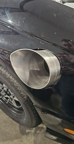
    The good news is that the pair of wide-band O2 sensors collects data and modifies fuel tables in real time. I was worried that the short collector length would create a condition where the sensors were sniffing some outside atmosphere vs actual exhaust. That doesn't seem to be happening. We were way too lean on the initial fuel tables. It was making the thing a real bitch to start. Turning on the O2s immediately fattened the motor by 25% once it was running.

    Once fired, we created an additional table to try and lean it out a bit so that it'll make some heat quickly while at idle. The intent being to warm the thing up faster and to mitigate fuel contamination to the oil. (methanol is notorious for pissing past the rings and collecting in the oil. I have a couple ideas on how to reduce this further. The oil tank has a heater. We're keeping it plugged in between rounds with the cap off to sweat fuel/water out of the oil. Next, the burn-down breathers I made are QD style. I can disconnect them from the valve covers. I made an additional plug that adapts to a shop vac hose. Between rounds, we'll hook it up and turn the vacuum on to pull fuel/water vapor out of the crank case.

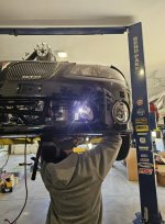
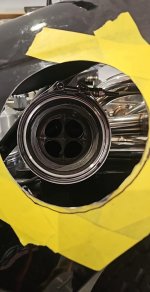
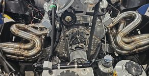
    Lots of work to do yet, but at least it makes noise now. It idles surprisingly well for an engine with a .800" lift/290* duration camshaft. Having heads that can actually move some air sure has seemed to tone down the harsh "snap" that the exhaust used to have. 2-1/4" primaries to a 4-1/2" collector probably helps a bunch too.

     
    Last edited: