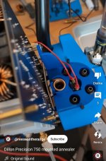
Has anyone been successful in getting a larger screen to work? I was looking into this when I first built the annealer I guess over a year ago and didn't have much success. I know in prior posts the author mentioned that he would have to update the libraries and that would take more memory etc, but here is a video of a guy running a larger screen.
Larger Screen
Unfortunately he doesn't show what he did and doesnt answer questions, not sure if he even speaks english. I have this screen that works really well if you just plug the screen into the arduino board with the code, once you plug the arduino into the nzhs board the screen doesn't work anymore. I really would like to know how that guy got the screen to work.
There are a couple of changes you have to make to your screen to make it an I2C board but its pretty simple. I saw a video on that here which is more thorough.
Board Conversion