I've made a few different ones for mine, mainly so it was short so I could position 6BR cases in a good spot. The latest one I made smaller diameter, around 3/4" on the inside with the outer coils wrapped pretty tightly around the inner ones, 7 1/2 coils in total. It works very well, I had to drop the voltage to 39v or it melted a 223 case neck in 2 seconds. It now runs 2.3 seconds for a 223 case.
Do you know what your current draw is on this? Fellow aussie and just built mine. Playing around with 3mm coils at the moment, but I can't seem to get below 8sec for 6.5CM brass.
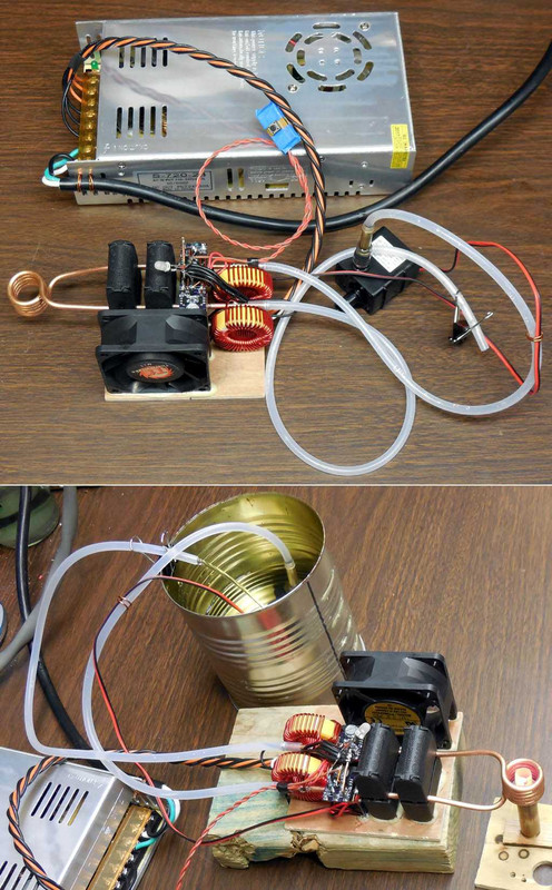
I'm seeing around 13amps currently. Going to try some 2 layer coil designs.
I also bought a 6mm 2 layer coil from AliExpress that I'm going to give a try.
Edit:
Looks like I have cracked the code for my own setup.
I just wound this coil and did a quick test (no water etc connected) and it had a 6.5CM case neck glowing in a few seconds.
So I don't think I will bother trying the one above now.
Specs:
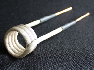
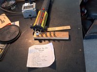
3mm copper, insulation pre-installed (yes I have fibres in my fingers, thanks for asking) and wound around a 25mm mandrel (3D printed), so probably ~26mm ID.
2 Layers
Inside Layer - 4 turns
Outside Layer - 3.5 turns
Aside from making the new coil, there's some other changes that could be affecting this.
1) I changed from approx 12 AWG wire to 10 AWG wire. I doubt this has made any difference though as the old wire didn't even get warm, so it wasn't struggling to carry the current.
2) The ZVS is just sitting outside the case for testing. This could have had an impact as there is zero metal near it. I previously had the coil running through a metal cover with a 3D printed plastic cover over it with smaller holes to stop shorting. I've cut a much bigger hole now and will use a 100mmx120mm 3D printed cover so it should not impact it now.
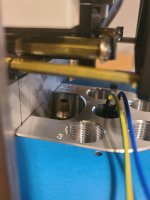
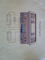
Also, for those of you who can't find a solution to fit beefy wires to small components like the current sensors, here is what I did.
Snip a connector and fold it over on itself. I added some solder afterwards to make it a bit more solid and able to carry the current.
The red lines are where I snipped.
Conveniently, the connector ends up with a bend in it so you can install them opposite ways and they have plenty of clearance.


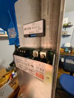

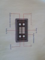

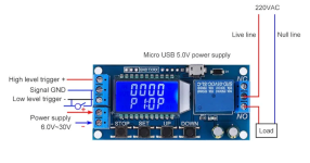
 Exactly my setup
  . Mine is dc... I have to power it with an phone charger at 5 V