• Watch Out for Scammers!

    We've now added a color code for all accounts. Orange accounts are new members, Blue are full members, and Green are Supporters. If you get a message about a sale from an orange account, make sure you pay attention before sending any money!

Need some CNC expert review on custom chassis weights

KZP

P.L.O.
Supporter
Banned !
Minuteman
Mar 11, 2017
4,241
10,006
NC
I know little about CNC and have been learning the basics over the past month.

I'm working on a chassis weight for the Tremor 50 using their custom rail system. Made two 3d prints to check clearance and fit. Now I'm ready to get a pair cut in 360 brass to see how well they hold up. Testing jerry rigged weights I find 9lb total added on is much more comfortable. One of these is 4.6~ lb, two can be mounted.

Xometry.com is easy to get setup on so that's what I've been using. They are quoting $265 each made internationally (probably China) and double for that USA with 0.1mm tolerance in about 20 locations, 3.2um finish. Part is 300mm x 55mm x 17.75mm. That seems like the best deal I am going to find along with fairly quick turn around of 2 weeks, but if anyone has other places to check that would be great.

From what can be seen below, are there any obvious rule of thumb violations for CNC design? The filet corners are setup for a 4mm ball end mill.

1647355772831.png


1647354840253.png


1647355316177.png
 
  • Like
Reactions: Makinchips208
That looks like a pretty easy job. A pocketing op with an end mill and a 3d waterline contour or similar using a ballmill. I don't see anything that would given even a minimally competent VMC operator any trouble.

When modeling parts like that, it can be helpful to size those internal fillets with standard ball mill sizes in mind. For example, a fillet with a .125" radius is one pass with a 1/4" ball mill, but a fillet with a .123" radius is lots of passes with a 1/8" ball mill.
 
Last edited:
That looks like a pretty easy job. A pocketing op with an end mill and a 3d waterline contour or similar using a ballmill. I don't see anything that would given even a minimally competent VMC operator any trouble.

When modeling parts like that, it can be helpful to size those internal fillets with standard ball mill sizes in mind. For example, a fillet with a .125" radius is one pass with a 1/4" ball mill, but a fillet with a .123" radius is lots of passes with a 1/8" ball mill.

I've been working in millimeter as the chassis was cut that way. I'm probably going to use the "international" production option as it's half cost and this is just a test run. Filet is set for 4mm ball mill, is that considered odd size?
 
I've been working in millimeter as the chassis was cut that way. I'm probably going to use the "international" production option as it's half cost and this is just a test run. Filet is set for 4mm ball mill, is that considered odd size?

Nope. 4mm ball mills are cheap and plentiful.


I believe that even those fillets that jboomhauer pointed out could be milled with a 3 axis vmc if the guy running the cam software is pretty good.

But, cleaning it up would make it easier, for sure. As it is, there will be lots of stepovers to get a decent finish on those angled walls.

If you can make them look like in boomhauers pic, it would help.
 
  • Like
Reactions: KZP
Looking pretty good to me.
I would change your print dimensions though.
Call all the mloc and bolt holes with respective lengths from a common point. Some one could stack your tolerances and have a part “to print” but unusable.
 
  • Like
Reactions: KZP and JBoomhauer
Looking pretty good to me.
I would change your print dimensions though.
Call all the mloc and bolt holes with respective lengths from a common point. Some one could stack your tolerances and have a part “to print” but unusable.
Great point there.

Also might want to consider adding a surface finish if you think they will ballnose the angles. That way they don’t pick a huge step over to get it out the door quicker.
 
Looking pretty good to me.
I would change your print dimensions though.
Call all the mloc and bolt holes with respective lengths from a common point. Some one could stack your tolerances and have a part “to print” but unusable.

I bet you just saved me hundreds of dollars and weeks of waiting. Didn't consider that but I can see it happening now. I will fix all those.

Great point there.

Also might want to consider adding a surface finish if you think they will ballnose the angles. That way they don’t pick a huge step over to get it out the door quicker.

The standard surface finish is 3.2 μm Ra, it's only a little more money to get 1.6 μm Ra all over which I can swing.

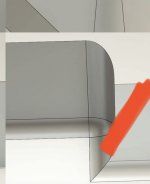
This all all great stuff, thanks for helping. Just to confirm that corner is wonky, here is another angle. This is simply selecting those edges in fusion 360 and setting filet 2mm. If these screenshots confirm it's goofy for a machine to make, I'll try to find another geometry for that corner. It's not super important it be exactly this, it's just a loose tolerance clearance cut.

corner_weight01.jpg
 
If you can put the same angle on this wall as the side wall, you can use one angle tool to cut the all the pocket walls. Saves from a waterline path that takes a bit of time to run.
BA78DC29-C82A-4F7E-B60B-BD48BE7ABE49.jpeg
 
If you can put the same angle on this wall as the side wall, you can use one angle tool to cut the all the pocket walls. Saves from a waterline path that takes a bit of time to run.
View attachment 7828370
I agree with that. And the same could be said for the straight wall at the opposite end of the part? Unless I’m not seeing that right. I think this is able to be manufactured as is, but it could be done easier.
Additionally if the inside radius is not critical, or not structural, it could be left sharp or radiused, whichever became easier. For example, just list max allowable radius is 4mm on the inside. But that isn’t a big issue as it is.
Hope that makes sense...

Edit. On second thought, I’m not trying to say redesign, it looks like you got a very nice part, and it is certainly machinable. A couple minutes with one operation vs another is small fries in the big picture. Especially if it’s a one off. Might be another issue if you wanted high volume.
 
Last edited:
  • Like
Reactions: KZP and JBoomhauer
If you can put the same angle on this wall as the side wall, you can use one angle tool to cut the all the pocket walls. Saves from a waterline path that takes a bit of time to run.
View attachment 7828370

Got it, I'll uniform all those walls like that.

I agree with that. And the same could be said for the straight wall at the opposite end of the part? Unless I’m not seeing that right. I think this is able to be manufactured as is, but it could be done easier.
Additionally if the inside radius is not critical, or not structural, it could be left sharp or radiused, whichever became easier. For example, just list max allowable radius is 4mm on the inside. But that isn’t a big issue as it is.
Hope that makes sense...

Edit. On second thought, I’m not trying to say redesign, it looks like you got a very nice part, and it is certainly machinable. A couple minutes with one operation vs another is small fries in the big picture. Especially if it’s a one off. Might be another issue if you wanted high volume.

Yeah this is a one off, but it's nice to learn the correct practices for future projects.
 
The prices xometry charge are crazy. They can do good work but they’re not worth the upcharge.

If you don’t care about them being made stateside partzpro.com will give you the best prices (half what you’ve been quoted) and they’re quick. I have used them for quick prototyping in the past and for small production runs of non firearm related stuff and they’ve been really good.
Fathom is another good alternative to xometry that’s just as easy to use and I’ve had success with in the past.
 
  • Like
Reactions: KZP