• Watch Out for Scammers!

    We've now added a color code for all accounts. Orange accounts are new members, Blue are full members, and Green are Supporters. If you get a message about a sale from an orange account, make sure you pay attention before sending any money!

Tuner Data

LOL @ 5 shot groups.

Data gentleman.....real data.

Also, you'll want to do several things. Shoot his rifle/rail. And also start from scratch with several other rifles.

You'll want blind shooting as well as known. You'll want to be able to identify any placebo effects and such. And you'll want several shooters from different experience levels.


Otherwise, you'll post data that suffers from the same problems currently.


I'd highly suggest submitting the proposed testing to a qualified research scientist to give any recommendations. Someone who is NOT Litz or with AB.

That will prevent any claims of sabotage.
 
Why would we do load development on site and without a tuner?
Why don't we use my gun with my ammo and tuner?
I shoot 5 targets at 5 shots remove the tuner from the barrel and you shoot 5 targets at 5 shots each?
Then I put the tuner back on and we repeat this several times.
If you have suggestions let’s get litz on the phone and see what sample size he suggests as well as protocols.

Then we can make a decision, get down there are do it right ..nothing is gained by “half assed” attempts.
 
  • Like
Reactions: kthomas
Ok, back in the saddle for 15min tonight. Don’t have the time I had yesterday. Want to still make some progress documenting exactly what you mean.

So, regarding #4 here and your response here, if you want the muzzle to be rising when you shoot, why would you also want the muzzle to be stationary?
Now we are getting things mixed up. We want the muzzle rising and we want the node of a standing wave at the muzzle. A standing wave appears stopped at segments along its length just like the pivot point of a teeter totter. It appears stopped.
That is why Dr Kolbey didn't agree with Bill Calfees article but I later clarified it for him.
How long of an article can I post here?
 
LOL @ 5 shot groups.

Data gentleman.....real data.

Also, you'll want to do several things. Shoot his rifle/rail. And also start from scratch with several other rifles.

You'll want blind shooting as well as known. You'll want to be able to identify any placebo effects and such. And you'll want several shooters from different experience levels.


Otherwise, you'll post data that suffers from the same problems currently.


I'd highly suggest submitting the proposed testing to a qualified research scientist to give any recommendations. Someone who is NOT Litz or with AB.

That will prevent any claims of sabotage.
Neither of you read his book or followed his 50 minute podcast even though you worship him but I'm not surprised in the least.

Bryan Litz tests where 5 shot groups of 5 targets and ebar48 can testify to that fact.
Where do you trolls come from?
 
Carbonbased
The problem with all this is we don't have a failure to communicate we don't have statistical or data issues the problem here is we have 5 trolls winging it as they go along for whatever reason and they all worship Bryan litz for some reason.
Probably a nice guy and his shooting stands on its own merits but these guys haven't done a quarter ounce of effort on anything ever.
 
How long of an article can I post here?
I’m not sure. Worst that can happen is the system errors out. Had that happen trying to upload jpgs that are too large.

Before you post any long thing…since math is not my strong suit, just pretend I’m some dunce and draw a sketch. Those are helpful. This is for that hypothesis I posted a whole back so it doesn’t have to be very detailed.

If we get to designing an experiment, that’s when the nitty-gritty details would be stated.
 
You're not supposed to come on this thread and prove that these guys are straight up liars. How dare you
Uhhh lol wasn’t trying to do anything. Did someone say it wasn’t available or something? I’ve just seen you mention it a bunch.
 
The Vibrations of a Barrel Tuned for Positive Compensation(Updated 18th November 2015)


"The art of producing extreme rimfire accuracy is at its best when informed by science."


Introduction
Mr A. Mallock ("Vibrations of Rifle Barrels", Proceedings of the Royal Society, Vol. 68, page 327, 1901) may not have been the first person to put forward the proposition that a rifle can be "tuned" to generate "positive compensation" at a given range, but it shows that this idea has been around for well over a century and is not a new one.
The proposition for positive compensation is based on the fact that when any given batch or type of ammunition is chronographed, there is a always a spread in muzzle velocity observed about a mean. As a consequence, there will be a vertical dispersion in the fall of shot at the target, as the slower bullets in the sample take longer to travel down the range and so drop further than the faster bullets. It is easy to compute what the vertical dispersion should be for a given batch of ammunition due to the observed spread in muzzle velocity.
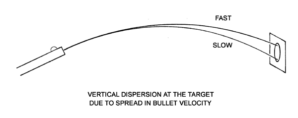
Vertical dispersion due to velocity spread
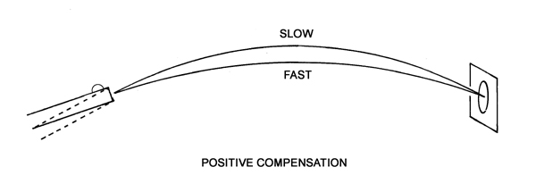
Curiously though, it is also often - if not usually - observed that the calculated vertical dispersion is not evident on the target. To explain this observation, the concept of "positive compensation" is invoked. It is generally recognised that the shock of the recoil forces in the rifle generate transverse vibrations in the barrel. For positive compensation, it is envisaged that the bullet is exiting the muzzle during an upward swing in the vibration at the muzzle, such that faster bullets (which arrive at the muzzle slightly earlier than slow bullets) are launched at a slightly lower angle into their trajectory than slower bullets. This will tend to reduce the vertical dispersion in the group at the target resulting from the variation in muzzle velocity. And if the upward swing in the muzzle is exactly right, there will be complete positive compensation as the trajectories of bullets across the entire spread of muzzle velocities all meet at the same height on the target at a given range.

Positive compensation representation

If there is (almost) general agreement on the principle, the many attempts since Mallock's paper to be more quantitative about the actual vibrations on a rifle barrel, and how they may be controlled to produce positive compensation, have left us little further forward than we were a century ago. Some attacks of note are summarised below.
The earliest attempt of note to measure vibrations on a rifle barrel (a Model 71 Mauser) was that of Cranz and Koch (�Untersuchungen uber die Vibration des Gewehrlaufs.� Abhandlungen d. math-phys. C1 D. Akedemie Der Wissenachaften, Vol. 69, page 747-775, Munchen, 1899.) who used high-speed photography to follow the motion of a wire attached to various parts of the barrel.
In 1912, Francis Carnegie ("The Vibration of Rifle-Barrels", Min. of Proc. of Inst. of Civ. Eng., Vol. 191, page 217-255, 1912-13 Pt. 1) built on the work of earlier experimenters (cited therein) in using a camera focused on a back-lit pin-hole which had been drilled in a thin sheet of metal attached to the barrel of the rifle. The vertical excursions of the barrel were thus recorded as the rifle recoiled to give the time-base on the photographic plate. Their test subject was the S.M.L.E. .303 service rifle, both stocked and de-stocked. They achieved some good results - notwithstanding the variable nature of the time-base of data obtained in this way, and that the fact that the barrel did vibrate before the bullet exited the barrel was firmly established.
Following on from Carnegie's work, a very determined effort was made to study the dynamics of a rifle under recoil at Woolwich Arsenal during the early 1920s. This work was finally published as an internal report. ("On Rifle Barrel Vibrations and their Effect on the Angle of Jump", R.D. Report No. 63, 1925) They also used the S.M.L.E. rifle as their test subject and showed how careful experimental methods can yield very useful results even when using comparatively primitive methods. In fact, it would be a long time before their results were bettered. This report was only de-classified in 1959.
In 1927, Captain Philip P. Quale used an oscillograph* for his attempt to measure the vibrations on the barrel of a 1903 Springfield ("The Vibrations of Rifle Barrels", American Rifleman, January 1, page 17-32, 1927).
(*An immediate predecessor to the cathode ray oscilloscope, but using a high speed drum camera to record the movements of a beam of light bouncing off a small mirror, which was attached to a coil suspended between two powerful magnets.)
A decade later, A.E. Martin and J. Muir ("Vibrations of a Rifle Barrel", Journal of the Royal Technical College Glasgow, Vol. 4, Part 2, page 213-239, 1938) used a cathode ray oscilloscope (a novel instrument in 1938) to measure the excursions of a phonograph needle, placed on the muzzle of a Lee-Enfield .303 rifle. They compared their results to the resonant frequencies of transverse waves on a uniform steel bar of similar dimensions to the rifle barrel, with results that were suggestive at best. The dynamic behaviour of a rifle barrel responding to a complex, impulsive, bending moment at one end, was (and is) not tractable in an analytic form and the computing power to tackle the problem numerically would not be available for another thirty years.
Harold Vaughn ("Rifle Accuracy Facts", Pub. Precision Shooting Inc. Connecticut, 1998) took another tilt at the problem. For his experimental work, Vaughn used an accelerometer on the muzzle of the barrel. The resulting trace of acceleration with time had to be integrated - once to obtain the vertical velocity of the muzzle, and again to get at the position with time. These results were of limited use by themselves. The main value of Vaughn's experimental results was to check his theoretical computer model, which used a numerical "lumped parameter" approach to model the rifle barrel vibrations. The results were more convincing than those of Martin and Muir, sixty years before, but it was clear that Vaughn's computer model was not reproducing the dynamics of the rifle barrel with sufficient accuracy to be useful in the problem of achieving positive compensation by design.
The increasingly powerful computers of modern times has enabled various interested individuals to run highly sophisticated Finite Element Analysis (FEA) computer simulations of rifle barrel dynamics as the bullet is travelling up the barrel. Probably the most sophisticated computer simulation to date is that run by Al Harral using the LS-Dyna FEA code. This code was developed at Lawrence Livermore National Laboratories, where Al Harral worked using the LS-Dyna code to analyse mechanical structures. Al Harral realised the potential of harnessing the muzzle vibrations to achieve positive compensation at a given range and has attempted to design barrels specifically contoured to give the desired result. His work has lacked the experimental confirmation needed to verify his computer modelling, however.
Also notable amongst these campaigns using FEA modelling of rifle barrels is that of Kevin N. Schwinkendorf and Steven P. Roblyer ("Simulation of the Vibrational Response of a Rifle Barrel During Firing", Proceedings of the Advanced Simulation Technologies Conference, organized by the Society for Computer Simulation, page 66, April 5-9, 1998). It was the belief of these two authors that if the muzzle vibration could be "tuned", so that if the rate of change of muzzle angle was minimised (zero) at the time of bullet exit, the vertical dispersion of the group at the target due to the variation in muzzle velocity would be minimised. This assumption is only justified if the launch time of the bullet with reference to the vibration cycling on the barrel does not change with muzzle velocity. They ran simulations for various muzzle weights to tune the vibrations for a null at the bullet exit time. Practical tests were to follow to verify the simulation, but to my knowledge no results of any such tests have been published.
The influential American rimfire gunsmith Bill Calfee, in an article written for Precision Shooting Magazine ("I'm Feeling Those Good Vibrations AGAIN!" Vol. 52, No. 11, March 2005) presented a rather novel view on how barrels vibrate, and also expressed his belief that for best accuracy, barrels should be tuned so that the muzzle is "stopped" and there is no change in muzzle angle, or position, as the bullet is launched. It should be noted that Calfee's theories have absolutely no basis in fact and are mathematically untenable. But that does not stop it being the most quoted work in the popular press on barrel vibrations and the tuning of barrels.
Despite the increasing sophistication of the attack on the theoretical modelling of rifle barrel vibrations in recent years, experimental work of comparable accuracy to check the computer models has been notable in its absence. The work presented here is an attempt to start redressing the balance between experiment and theory so that future theoretical work can be better informed.
The apparatus
It is clear that the variable that is required to be measured is the angle of the muzzle of the barrel to the horizontal, and the way this varies with time as the bullet exits the barrel. All the experimental attempts listed above have measured the position, velocity, or acceleration of a point on the rifle barrel. The best these results could hope to do was inform a theoretical model which could calculate the rate of change of angle at the muzzle, but which could also generate data on the predicted position, velocity and acceleration at any point on the barrel with time with which the experimental results could be compared. It would be helpful to have experimental results that could stand alone as a useful tool in determining the optimum vibrations for positive compensation, rather than be a test of a theoretical model which would be depended on to generate the useful information.
Using a mirror attached to the muzzle in some way, so as to reflect a beam of light, is an obvious route. The excursions of the reflected beam would be a direct function of the vibrations of the barrel at the mirror, and could be measured in a number of ways. However, such an apparatus would be difficult to set up and very cumbersome, as its sensitivity would proportional to its size and the angular variation expected is small.
The method finally chosen was to attach a thin sheet of polarising plastic to the muzzle. Beams of light would be shone through the polarising sheet onto polarised detectors. If the planes of polarisation of the polarising plastic sheet and the polarised detectors were set at 45 degrees, the change in signal in the detectors would be proportional to the change in angle of the polarising sheet - and so the muzzle of the barrel. By using two detectors polarised at 90 degrees to each other and combining the two signals in a differential amplifier, the signal would also be insensitive to any common-mode changes such as in the intensity of the light sources.

Principle of apparatus

Such an apparatus could be compact, sensitive, easy to set up, and would have the added benefit that it would only be sensitive to changes in angle of the polarising plastic sheet about an axis perpendicular to the plane of the sheet. It would not be sensitive to any other degree of freedom such as a change in position either up-down, backwards-forwards or sideways or rotation about any other orthogonal axis.
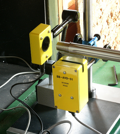
Experimental setup

A "muzzle gate" was also required to detect the exact moment the bullet exited the barrel. This was a simple photoelectric device, using photodiodes to detect the interruption of light from an LED array as the bullet passed between them. The experimental setup is shown above. The polarising sheet is attached temporarily to the bottom of the barrel using "Blu-Tac", a malleable plastic adhesive. The bottom of the sheet is seen sitting in the slot of the sensor head, which contains the light sources, the polarised detectors and the first stages of the differential amplifier. The muzzle gate is seen sitting in front of the muzzle of the barrel. A contact microphone is attached to the action using a magnet and this detects the sound of the firing pin hitting the case. This signal is used to trigger the digital oscilloscope used to record the signals from the sensor head and the muzzle gate.
Exit time variation
Variation of muzzle velocity with bullet exit time
The first step in deducing what rate of change of angle at the muzzle is required to give positive compensation, is to know how the exit time of the bullet at the muzzle varies with muzzle velocity.
For this experiment, the muzzle velocity was determined using an Ohler 35 chronograph. The two sky screens were separated by four feet and they were centred on a point five feet ahead of the muzzle. The absolute value of the muzzle velocity was not too critical for this experiment as it was the differences in muzzle velocity that were of interest. Because of this, it was important that the 'jitter' on the measured muzzle velocity was minimised. In an attempt to minimise the jitter of the chronograph, an LED array forming a 'light bar' 6 inches long and of width 0.08", was placed 8 inches above each sky screen. This formed a thin light source above each sky screen of uniform and constant brightness along its length.
To measure the variation in bullet exit time from the muzzle, it would seem obvious to measure the variation in the interval between the contact microphone trigger signal (ie when the firing pin struck the case) and the bullet passing through the muzzle gate. But it was expected that there would be some variation in the initiation in burning of the primer and powder after the fall of the firing pin. This variation could mask the looked for variation in bullet exit time, due to variation in muzzle velocity, to some significant extent. However, it is the pressures generated by the burning primer and powder that gives rise to the barrel vibrations. While variations in the pressures may alter the amplitude of the vibrations, it was considered that the time history of the barrel vibrations would remain constant as this would be due to the mechanical structure of the rifle itself, and this would not change from shot to shot. The best way to measure the variation in bullet exit time would be with reference to the barrel vibrations, rather than the trigger signal.
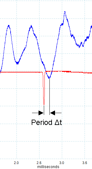
The trace on the right shows a portion of signal indicating the changing muzzle angle (blue) around the time when the bullet exited the muzzle, as indicated by the momentary downward 'blip' in the muzzle gate signal (red). The period 'delta t' from the muzzle gate signal to the following null in vibration signal was measured for each shot fired, along with the measured velocity.
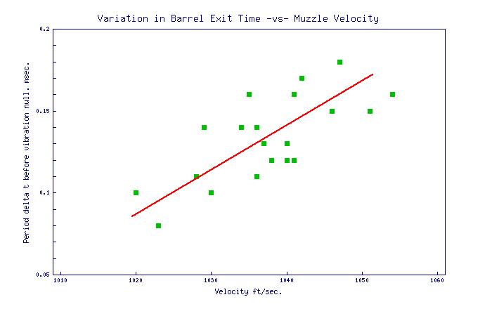
The graph below shows the results for Eley EPS Tenex ammunition. The data are rather noisy, but there is a fairly clear trend that for a change in muzzle velocity of 375 ft/sec., the exit time is changing by 1 millisecond. The barrel in this case was 26 inches long. This is expected to be a fairly universal constant applicable to all rimfire barrels of this length, shooting subsonic target ammunition.
Indeed, it may be that this is a universal constant for rimfire barrels of any length over six inches (approximately), after which friction is increasingly the dominant force on the bullet during its travel up the barrel. Thus, it can be argued that to first order, the spread in velocity of the bullets in the barrel will increase linearly with distance travelled up the barrel past the six inch point, and the rate of change of barrel travel time with velocity will remain fairly constant with length.

Variation in bullet exit time -vs- muzzle velocity

Variation in launch angle with muzzle velocity required for complete positive compensation at 50 metres
Using the Trajectory program, it is trivial matter to compute the change in muzzle angle required for complete positive compensation at 50 metres, for a given range of muzzle velocity. So, for a velocity of 1010 ft/sec. the launch angle needed is 9.3 MOA and for 1060 ft/sec. the required launch angle is 8.5 MOA to hit the target at the same height.
The rate at which the angle of the muzzle has to change with muzzle velocity, so all the shots hit the target at the same height and there is complete positive compensation, is 0.016 MOA for 1 ft/sec. change in muzzle velocity.
Rate of change of muzzle angle required for complete positive compensation at 50 metres
Multiplying together the Variation of muzzle velocity with bullet exit time and the Variation in launch angle with muzzle velocity required for complete positive compensation at 50 metres, the required rate of change of muzzle angle with time is 6.0 MOA per millisecond for a 26 inch barrel.


A case study
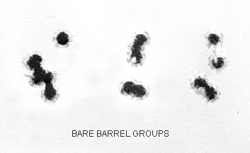
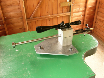
A barrelled action was placed in the Border Barrels test rig. (See the picture to the right). The barrel length was 26" and the diameter was 0.943". However, it was protruding only 17 inches in front of the barrel clamp, by which the barrelled action was attached to the rig. (Note that this rig was not rigid. The relatively thin base plate flexed under recoil and allowed the barrel clamp to rotate backwards, resulting in an upwards vertical muzzle flip.) Experience had shown that with such a short length of barrel ahead of the clamp, the groups with a bare barrel would be strung vertically. (The photo shows the barrel with a 200 gram weight clamped on it at the muzzle.) This barrel was no exception. It is clear from the three groups in the photo below that at 50 metres, using Eley EPS Tenex, the shots were stringing vertically.
Bare barrel groups
Test case barrel
Bare barrel vertical dispersion at the target

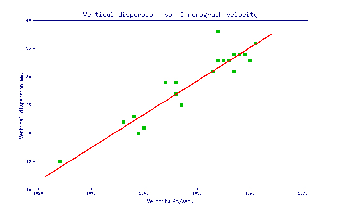
The graph above is a plot of the height of a number of shots above a randomly drawn line on the target, as a function of muzzle velocity. The red line is a fit through the data and has a slope showing a drop in height on the target of 0.595mm for each ft/sec. decrease in muzzle velocity. This is equivalent to 0.041 MOA for each ft/sec. decrease in muzzle velocity.
But there will naturally be a drop at the target of 0.016 MOA for every ft/sec. drop in muzzle velocity, just because the bullet takes a little longer to get there (see above). So it is assumed that the remaining 0.025 MOA for every ft/sec. change in muzzle velocity will be due to a change in the muzzle angle at bullet launch. It was shown above that the muzzle velocity varies with the exit time of the bullet at the muzzle at 375 ft/sec. per millisecond. As the bullets were exiting the muzzle of the bare barrel then, the muzzle must have been swinging downwards at a rate of 9.4 MOA per millisecond (0.025 MOA per ft/sec. multiplied by 375 ft/sec. per millisecond) to produce the observed vertical dispersion at the target.
Vibration of bare barrel
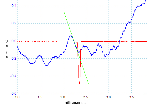
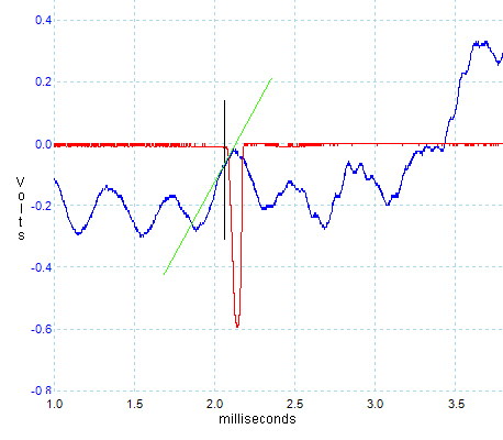
The image to the right is a trace of the rate of change of angle at the muzzle of the bare barrel, as taken using the apparatus described above. The blue trace is the angle of the muzzle. The vertical axis is in volts. The calibration determined during testing of the apparatus on the bench was that 0.16 volts is equivalent to 1 MOA. The red trace is the muzzle gate and the negative blip show when the bullet passed through the muzzle gate. But the muzzle gate was about one inch in front of the muzzle, so the actual moment when the bullet was exiting the muzzle would have been about 0.1 milliseconds earlier, where the black vertical line has been placed.
The green line set against the muzzle angle trace at the moment the bullet was exiting the barrel shows the rate at which the muzzle angle was changing at that time. The rate was -9.4 MOA per millisecond. This is in perfect agreement with the rate calculated from the vertical dispersion at the target above. The difference is that only one shot was required to determine this rate of change of muzzle angle using the apparatus described, whereas twenty shots were needed to determine it from the fall of shot on the target.
Vibrations with and without tuner
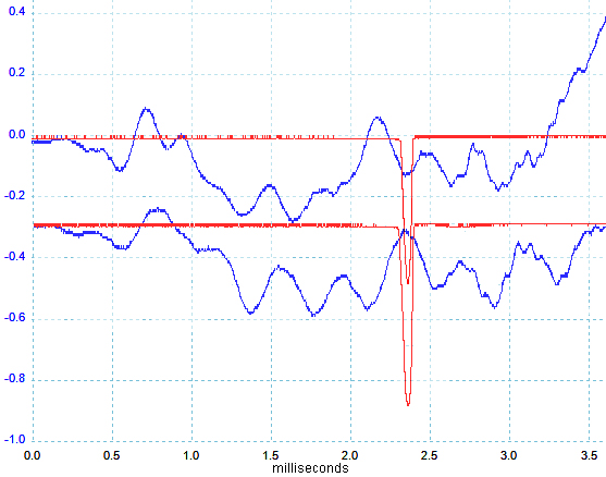
In the image on the right, the top trace is the barrel vibrations from the bare barrel, discussed above, and the bottom trace is the barrel which has now been "tuned" with a 200 gram weight attached to the front of the barrel. The traces have been superimposed so that the bullet exits appear at same time. As can be seen, the general shape or pattern of vibrations for the two traces is very similar. However, while the vibrations on the two traces start out in a very similar way, the pattern of vibrations with the weighted barrel appears slightly stretched in time compared to that of the unweighted barrel.
Looking at the vibration trace of the "tuned" barrel in more detail, the vertical black line once again shows the moment the bullet was exiting the barrel. The green line laid against the trace for that moment shows the rate at which the barrel was swinging upward in angle as the bullet exited barrel. The rate is 6.0 MOA per millisecond. This will be recognized from the discussion above as the exact rate required to give complete positive compensation at 50 metres.
In theory, this barrel with a 200 gram weight on the front should have perfect positive compensation at 50 metres. So, how did it shoot?
See the groups below.

Groups with tuner

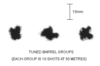
The groups are self evidently 'round', the spread now being primarily caused by dispersive forces due to factors such as the off-axis centre of gravity in the bullets, and the bullets being upset on launch due to the wash of the muzzle blast over their base. Unlike the dispersion caused due to variation in muzzle velocity, these forces have no preferred axis in which they act and so result in round groups. It is the roundness of the groups, being as wide as they are tall, (subject to the usual statistical uncertainties), which shows that vertical dispersion is no longer a significant factor.
Tuned barrel


Conclusions
It has been shown that the launch time of the bullet from the barrel, with reference to the transverse vibrations in the barrel, does vary with muzzle velocity, and this rate has been measured for Eley Tenex .22 rimfire ammunition in a 26 inch barrel. The proposition that positive compensation might be achieved by "tuning" a barrel, such that the muzzle angle is changing with time in a beneficial way at bullet launch, is thus a valid one.
In a test case, the vertical dispersion at a range of 50 metres was measured as a function of muzzle velocity for an "untuned" barrel. From this dispersion, and the known rate of change of launch time with muzzle velocity for a 26 inch barrel, a rate of change of angle at the muzzle for this barrel was calculated. Using an apparatus built to measure the rate of change of angle of a barrel, the rate of change of angle at the muzzle was measured and this agreed with that calculated from the group dispersion. This demonstrated that the apparatus was working as designed. It also showed that the vertical velocity of the muzzle is probably not significant in contributing to the vertical dispersion of the group in general, compared to the rate of change of muzzle angle, and was certainly not so in this case.
Finally, the barrel was "tuned" by attaching a weight to the front of the barrel, such that the rate of change of angle at the muzzle was now 6.0 MOA per millisecond at bullet launch, which is the rate of change required for complete positive compensation at 50 metres. The groups fired with the tuned barrel were small and round, showing no sign of vertical dispersion, so demonstrating that positive compensation had been achieved.
The measurement of barrel vibrations in the way demonstrated will be a very quick and positive method of tuning a rifle, requiring very few shots and very little time. Moreover, there is no ambiguity or uncertainty about the result. When the barrel is tuned for complete positive compensation, no further improvement is possible.
 
  • Like
Reactions: JAS-SH
Insulting someone's phone app means you've lost the debate
Maybe this is part of your struggle. If you take corrections and criticisms as insults, you'll never be able to have a meaningful debate, and you'll end up in similar situations to the one you're in now. That's a personal issue. One you have to work out on your own, or with a professional equipped to help with that specific problem.
 
Oh we're back to rimfire again, and 2015.
 
The Vibrations of a Barrel Tuned for Positive Compensation(Updated 18th November 2015)


"The art of producing extreme rimfire accuracy is at its best when informed by science."


Introduction
Mr A. Mallock ("Vibrations of Rifle Barrels", Proceedings of the Royal Society, Vol. 68, page 327, 1901) may not have been the first person to put forward the proposition that a rifle can be "tuned" to generate "positive compensation" at a given range, but it shows that this idea has been around for well over a century and is not a new one.
The proposition for positive compensation is based on the fact that when any given batch or type of ammunition is chronographed, there is a always a spread in muzzle velocity observed about a mean. As a consequence, there will be a vertical dispersion in the fall of shot at the target, as the slower bullets in the sample take longer to travel down the range and so drop further than the faster bullets. It is easy to compute what the vertical dispersion should be for a given batch of ammunition due to the observed spread in muzzle velocity.

Vertical dispersion due to velocity spread
Curiously though, it is also often - if not usually - observed that the calculated vertical dispersion is not evident on the target. To explain this observation, the concept of "positive compensation" is invoked. It is generally recognised that the shock of the recoil forces in the rifle generate transverse vibrations in the barrel. For positive compensation, it is envisaged that the bullet is exiting the muzzle during an upward swing in the vibration at the muzzle, such that faster bullets (which arrive at the muzzle slightly earlier than slow bullets) are launched at a slightly lower angle into their trajectory than slower bullets. This will tend to reduce the vertical dispersion in the group at the target resulting from the variation in muzzle velocity. And if the upward swing in the muzzle is exactly right, there will be complete positive compensation as the trajectories of bullets across the entire spread of muzzle velocities all meet at the same height on the target at a given range.

Positive compensation representation

If there is (almost) general agreement on the principle, the many attempts since Mallock's paper to be more quantitative about the actual vibrations on a rifle barrel, and how they may be controlled to produce positive compensation, have left us little further forward than we were a century ago. Some attacks of note are summarised below.
The earliest attempt of note to measure vibrations on a rifle barrel (a Model 71 Mauser) was that of Cranz and Koch (�Untersuchungen uber die Vibration des Gewehrlaufs.� Abhandlungen d. math-phys. C1 D. Akedemie Der Wissenachaften, Vol. 69, page 747-775, Munchen, 1899.) who used high-speed photography to follow the motion of a wire attached to various parts of the barrel.
In 1912, Francis Carnegie ("The Vibration of Rifle-Barrels", Min. of Proc. of Inst. of Civ. Eng., Vol. 191, page 217-255, 1912-13 Pt. 1) built on the work of earlier experimenters (cited therein) in using a camera focused on a back-lit pin-hole which had been drilled in a thin sheet of metal attached to the barrel of the rifle. The vertical excursions of the barrel were thus recorded as the rifle recoiled to give the time-base on the photographic plate. Their test subject was the S.M.L.E. .303 service rifle, both stocked and de-stocked. They achieved some good results - notwithstanding the variable nature of the time-base of data obtained in this way, and that the fact that the barrel did vibrate before the bullet exited the barrel was firmly established.
Following on from Carnegie's work, a very determined effort was made to study the dynamics of a rifle under recoil at Woolwich Arsenal during the early 1920s. This work was finally published as an internal report. ("On Rifle Barrel Vibrations and their Effect on the Angle of Jump", R.D. Report No. 63, 1925) They also used the S.M.L.E. rifle as their test subject and showed how careful experimental methods can yield very useful results even when using comparatively primitive methods. In fact, it would be a long time before their results were bettered. This report was only de-classified in 1959.
In 1927, Captain Philip P. Quale used an oscillograph* for his attempt to measure the vibrations on the barrel of a 1903 Springfield ("The Vibrations of Rifle Barrels", American Rifleman, January 1, page 17-32, 1927).
(*An immediate predecessor to the cathode ray oscilloscope, but using a high speed drum camera to record the movements of a beam of light bouncing off a small mirror, which was attached to a coil suspended between two powerful magnets.)
A decade later, A.E. Martin and J. Muir ("Vibrations of a Rifle Barrel", Journal of the Royal Technical College Glasgow, Vol. 4, Part 2, page 213-239, 1938) used a cathode ray oscilloscope (a novel instrument in 1938) to measure the excursions of a phonograph needle, placed on the muzzle of a Lee-Enfield .303 rifle. They compared their results to the resonant frequencies of transverse waves on a uniform steel bar of similar dimensions to the rifle barrel, with results that were suggestive at best. The dynamic behaviour of a rifle barrel responding to a complex, impulsive, bending moment at one end, was (and is) not tractable in an analytic form and the computing power to tackle the problem numerically would not be available for another thirty years.
Harold Vaughn ("Rifle Accuracy Facts", Pub. Precision Shooting Inc. Connecticut, 1998) took another tilt at the problem. For his experimental work, Vaughn used an accelerometer on the muzzle of the barrel. The resulting trace of acceleration with time had to be integrated - once to obtain the vertical velocity of the muzzle, and again to get at the position with time. These results were of limited use by themselves. The main value of Vaughn's experimental results was to check his theoretical computer model, which used a numerical "lumped parameter" approach to model the rifle barrel vibrations. The results were more convincing than those of Martin and Muir, sixty years before, but it was clear that Vaughn's computer model was not reproducing the dynamics of the rifle barrel with sufficient accuracy to be useful in the problem of achieving positive compensation by design.
The increasingly powerful computers of modern times has enabled various interested individuals to run highly sophisticated Finite Element Analysis (FEA) computer simulations of rifle barrel dynamics as the bullet is travelling up the barrel. Probably the most sophisticated computer simulation to date is that run by Al Harral using the LS-Dyna FEA code. This code was developed at Lawrence Livermore National Laboratories, where Al Harral worked using the LS-Dyna code to analyse mechanical structures. Al Harral realised the potential of harnessing the muzzle vibrations to achieve positive compensation at a given range and has attempted to design barrels specifically contoured to give the desired result. His work has lacked the experimental confirmation needed to verify his computer modelling, however.
Also notable amongst these campaigns using FEA modelling of rifle barrels is that of Kevin N. Schwinkendorf and Steven P. Roblyer ("Simulation of the Vibrational Response of a Rifle Barrel During Firing", Proceedings of the Advanced Simulation Technologies Conference, organized by the Society for Computer Simulation, page 66, April 5-9, 1998). It was the belief of these two authors that if the muzzle vibration could be "tuned", so that if the rate of change of muzzle angle was minimised (zero) at the time of bullet exit, the vertical dispersion of the group at the target due to the variation in muzzle velocity would be minimised. This assumption is only justified if the launch time of the bullet with reference to the vibration cycling on the barrel does not change with muzzle velocity. They ran simulations for various muzzle weights to tune the vibrations for a null at the bullet exit time. Practical tests were to follow to verify the simulation, but to my knowledge no results of any such tests have been published.
The influential American rimfire gunsmith Bill Calfee, in an article written for Precision Shooting Magazine ("I'm Feeling Those Good Vibrations AGAIN!" Vol. 52, No. 11, March 2005) presented a rather novel view on how barrels vibrate, and also expressed his belief that for best accuracy, barrels should be tuned so that the muzzle is "stopped" and there is no change in muzzle angle, or position, as the bullet is launched. It should be noted that Calfee's theories have absolutely no basis in fact and are mathematically untenable. But that does not stop it being the most quoted work in the popular press on barrel vibrations and the tuning of barrels.
Despite the increasing sophistication of the attack on the theoretical modelling of rifle barrel vibrations in recent years, experimental work of comparable accuracy to check the computer models has been notable in its absence. The work presented here is an attempt to start redressing the balance between experiment and theory so that future theoretical work can be better informed.
The apparatus
It is clear that the variable that is required to be measured is the angle of the muzzle of the barrel to the horizontal, and the way this varies with time as the bullet exits the barrel. All the experimental attempts listed above have measured the position, velocity, or acceleration of a point on the rifle barrel. The best these results could hope to do was inform a theoretical model which could calculate the rate of change of angle at the muzzle, but which could also generate data on the predicted position, velocity and acceleration at any point on the barrel with time with which the experimental results could be compared. It would be helpful to have experimental results that could stand alone as a useful tool in determining the optimum vibrations for positive compensation, rather than be a test of a theoretical model which would be depended on to generate the useful information.
Using a mirror attached to the muzzle in some way, so as to reflect a beam of light, is an obvious route. The excursions of the reflected beam would be a direct function of the vibrations of the barrel at the mirror, and could be measured in a number of ways. However, such an apparatus would be difficult to set up and very cumbersome, as its sensitivity would proportional to its size and the angular variation expected is small.
The method finally chosen was to attach a thin sheet of polarising plastic to the muzzle. Beams of light would be shone through the polarising sheet onto polarised detectors. If the planes of polarisation of the polarising plastic sheet and the polarised detectors were set at 45 degrees, the change in signal in the detectors would be proportional to the change in angle of the polarising sheet - and so the muzzle of the barrel. By using two detectors polarised at 90 degrees to each other and combining the two signals in a differential amplifier, the signal would also be insensitive to any common-mode changes such as in the intensity of the light sources.

Principle of apparatus

Such an apparatus could be compact, sensitive, easy to set up, and would have the added benefit that it would only be sensitive to changes in angle of the polarising plastic sheet about an axis perpendicular to the plane of the sheet. It would not be sensitive to any other degree of freedom such as a change in position either up-down, backwards-forwards or sideways or rotation about any other orthogonal axis.

Experimental setup

A "muzzle gate" was also required to detect the exact moment the bullet exited the barrel. This was a simple photoelectric device, using photodiodes to detect the interruption of light from an LED array as the bullet passed between them. The experimental setup is shown above. The polarising sheet is attached temporarily to the bottom of the barrel using "Blu-Tac", a malleable plastic adhesive. The bottom of the sheet is seen sitting in the slot of the sensor head, which contains the light sources, the polarised detectors and the first stages of the differential amplifier. The muzzle gate is seen sitting in front of the muzzle of the barrel. A contact microphone is attached to the action using a magnet and this detects the sound of the firing pin hitting the case. This signal is used to trigger the digital oscilloscope used to record the signals from the sensor head and the muzzle gate.
Exit time variation
Variation of muzzle velocity with bullet exit time
The first step in deducing what rate of change of angle at the muzzle is required to give positive compensation, is to know how the exit time of the bullet at the muzzle varies with muzzle velocity.
For this experiment, the muzzle velocity was determined using an Ohler 35 chronograph. The two sky screens were separated by four feet and they were centred on a point five feet ahead of the muzzle. The absolute value of the muzzle velocity was not too critical for this experiment as it was the differences in muzzle velocity that were of interest. Because of this, it was important that the 'jitter' on the measured muzzle velocity was minimised. In an attempt to minimise the jitter of the chronograph, an LED array forming a 'light bar' 6 inches long and of width 0.08", was placed 8 inches above each sky screen. This formed a thin light source above each sky screen of uniform and constant brightness along its length.
To measure the variation in bullet exit time from the muzzle, it would seem obvious to measure the variation in the interval between the contact microphone trigger signal (ie when the firing pin struck the case) and the bullet passing through the muzzle gate. But it was expected that there would be some variation in the initiation in burning of the primer and powder after the fall of the firing pin. This variation could mask the looked for variation in bullet exit time, due to variation in muzzle velocity, to some significant extent. However, it is the pressures generated by the burning primer and powder that gives rise to the barrel vibrations. While variations in the pressures may alter the amplitude of the vibrations, it was considered that the time history of the barrel vibrations would remain constant as this would be due to the mechanical structure of the rifle itself, and this would not change from shot to shot. The best way to measure the variation in bullet exit time would be with reference to the barrel vibrations, rather than the trigger signal.
The trace on the right shows a portion of signal indicating the changing muzzle angle (blue) around the time when the bullet exited the muzzle, as indicated by the momentary downward 'blip' in the muzzle gate signal (red). The period 'delta t' from the muzzle gate signal to the following null in vibration signal was measured for each shot fired, along with the measured velocity.
The graph below shows the results for Eley EPS Tenex ammunition. The data are rather noisy, but there is a fairly clear trend that for a change in muzzle velocity of 375 ft/sec., the exit time is changing by 1 millisecond. The barrel in this case was 26 inches long. This is expected to be a fairly universal constant applicable to all rimfire barrels of this length, shooting subsonic target ammunition.
Indeed, it may be that this is a universal constant for rimfire barrels of any length over six inches (approximately), after which friction is increasingly the dominant force on the bullet during its travel up the barrel. Thus, it can be argued that to first order, the spread in velocity of the bullets in the barrel will increase linearly with distance travelled up the barrel past the six inch point, and the rate of change of barrel travel time with velocity will remain fairly constant with length.

Variation in bullet exit time -vs- muzzle velocity

Variation in launch angle with muzzle velocity required for complete positive compensation at 50 metres
Using the Trajectory program, it is trivial matter to compute the change in muzzle angle required for complete positive compensation at 50 metres, for a given range of muzzle velocity. So, for a velocity of 1010 ft/sec. the launch angle needed is 9.3 MOA and for 1060 ft/sec. the required launch angle is 8.5 MOA to hit the target at the same height.
The rate at which the angle of the muzzle has to change with muzzle velocity, so all the shots hit the target at the same height and there is complete positive compensation, is 0.016 MOA for 1 ft/sec. change in muzzle velocity.
Rate of change of muzzle angle required for complete positive compensation at 50 metres
Multiplying together the Variation of muzzle velocity with bullet exit time and the Variation in launch angle with muzzle velocity required for complete positive compensation at 50 metres, the required rate of change of muzzle angle with time is 6.0 MOA per millisecond for a 26 inch barrel.​


A case study
A barrelled action was placed in the Border Barrels test rig. (See the picture to the right). The barrel length was 26" and the diameter was 0.943". However, it was protruding only 17 inches in front of the barrel clamp, by which the barrelled action was attached to the rig. (Note that this rig was not rigid. The relatively thin base plate flexed under recoil and allowed the barrel clamp to rotate backwards, resulting in an upwards vertical muzzle flip.) Experience had shown that with such a short length of barrel ahead of the clamp, the groups with a bare barrel would be strung vertically. (The photo shows the barrel with a 200 gram weight clamped on it at the muzzle.) This barrel was no exception. It is clear from the three groups in the photo below that at 50 metres, using Eley EPS Tenex, the shots were stringing vertically.
Bare barrel groups
Test case barrel
Bare barrel vertical dispersion at the target

The graph above is a plot of the height of a number of shots above a randomly drawn line on the target, as a function of muzzle velocity. The red line is a fit through the data and has a slope showing a drop in height on the target of 0.595mm for each ft/sec. decrease in muzzle velocity. This is equivalent to 0.041 MOA for each ft/sec. decrease in muzzle velocity.
But there will naturally be a drop at the target of 0.016 MOA for every ft/sec. drop in muzzle velocity, just because the bullet takes a little longer to get there (see above). So it is assumed that the remaining 0.025 MOA for every ft/sec. change in muzzle velocity will be due to a change in the muzzle angle at bullet launch. It was shown above that the muzzle velocity varies with the exit time of the bullet at the muzzle at 375 ft/sec. per millisecond. As the bullets were exiting the muzzle of the bare barrel then, the muzzle must have been swinging downwards at a rate of 9.4 MOA per millisecond (0.025 MOA per ft/sec. multiplied by 375 ft/sec. per millisecond) to produce the observed vertical dispersion at the target.
Vibration of bare barrel
The image to the right is a trace of the rate of change of angle at the muzzle of the bare barrel, as taken using the apparatus described above. The blue trace is the angle of the muzzle. The vertical axis is in volts. The calibration determined during testing of the apparatus on the bench was that 0.16 volts is equivalent to 1 MOA. The red trace is the muzzle gate and the negative blip show when the bullet passed through the muzzle gate. But the muzzle gate was about one inch in front of the muzzle, so the actual moment when the bullet was exiting the muzzle would have been about 0.1 milliseconds earlier, where the black vertical line has been placed.
The green line set against the muzzle angle trace at the moment the bullet was exiting the barrel shows the rate at which the muzzle angle was changing at that time. The rate was -9.4 MOA per millisecond. This is in perfect agreement with the rate calculated from the vertical dispersion at the target above. The difference is that only one shot was required to determine this rate of change of muzzle angle using the apparatus described, whereas twenty shots were needed to determine it from the fall of shot on the target.
Vibrations with and without tuner
In the image on the right, the top trace is the barrel vibrations from the bare barrel, discussed above, and the bottom trace is the barrel which has now been "tuned" with a 200 gram weight attached to the front of the barrel. The traces have been superimposed so that the bullet exits appear at same time. As can be seen, the general shape or pattern of vibrations for the two traces is very similar. However, while the vibrations on the two traces start out in a very similar way, the pattern of vibrations with the weighted barrel appears slightly stretched in time compared to that of the unweighted barrel.
Looking at the vibration trace of the "tuned" barrel in more detail, the vertical black line once again shows the moment the bullet was exiting the barrel. The green line laid against the trace for that moment shows the rate at which the barrel was swinging upward in angle as the bullet exited barrel. The rate is 6.0 MOA per millisecond. This will be recognized from the discussion above as the exact rate required to give complete positive compensation at 50 metres.
In theory, this barrel with a 200 gram weight on the front should have perfect positive compensation at 50 metres. So, how did it shoot?
See the groups below.

Groups with tuner

The groups are self evidently 'round', the spread now being primarily caused by dispersive forces due to factors such as the off-axis centre of gravity in the bullets, and the bullets being upset on launch due to the wash of the muzzle blast over their base. Unlike the dispersion caused due to variation in muzzle velocity, these forces have no preferred axis in which they act and so result in round groups. It is the roundness of the groups, being as wide as they are tall, (subject to the usual statistical uncertainties), which shows that vertical dispersion is no longer a significant factor.
Tuned barrel


Conclusions
It has been shown that the launch time of the bullet from the barrel, with reference to the transverse vibrations in the barrel, does vary with muzzle velocity, and this rate has been measured for Eley Tenex .22 rimfire ammunition in a 26 inch barrel. The proposition that positive compensation might be achieved by "tuning" a barrel, such that the muzzle angle is changing with time in a beneficial way at bullet launch, is thus a valid one.
In a test case, the vertical dispersion at a range of 50 metres was measured as a function of muzzle velocity for an "untuned" barrel. From this dispersion, and the known rate of change of launch time with muzzle velocity for a 26 inch barrel, a rate of change of angle at the muzzle for this barrel was calculated. Using an apparatus built to measure the rate of change of angle of a barrel, the rate of change of angle at the muzzle was measured and this agreed with that calculated from the group dispersion. This demonstrated that the apparatus was working as designed. It also showed that the vertical velocity of the muzzle is probably not significant in contributing to the vertical dispersion of the group in general, compared to the rate of change of muzzle angle, and was certainly not so in this case.
Finally, the barrel was "tuned" by attaching a weight to the front of the barrel, such that the rate of change of angle at the muzzle was now 6.0 MOA per millisecond at bullet launch, which is the rate of change required for complete positive compensation at 50 metres. The groups fired with the tuned barrel were small and round, showing no sign of vertical dispersion, so demonstrating that positive compensation had been achieved.
The measurement of barrel vibrations in the way demonstrated will be a very quick and positive method of tuning a rifle, requiring very few shots and very little time. Moreover, there is no ambiguity or uncertainty about the result. When the barrel is tuned for complete positive compensation, no further improvement is possible.
So, here is the article that @cameljockey230 pasted above:

On its webpage it’s a little easier to read. It’s a bit too technical for me to quickly understand.

Who is the author, by the way? His homepage is here: http://www.geoffrey-kolbe.com/
 
Last edited:
Oh we're back to rimfire again, and 2015.
I think his point is that rimfires react the same as center fires but due to less recoil force the amplitude is less. So we could extrapolate the same data on a comparative basis .
 
  • Like
Reactions: Tokay444
Maybe this is part of your struggle. If you take corrections and criticisms as insults, you'll never be able to have a meaningful debate, and you'll end up in similar situations to the one you're in now. That's a personal issue. One you have to work out on your own, or with a professional equipped to help with that specific problem.
Here is the problem.
It's not a debate at all. Several people here are teaching you something that is actually old news to most competitive shooters.
Your shooting experience hasn't advanced you enough to understand the developments and advancements of 20 years ago which is okay of you have an open mind to learning but unfortunately you don't.
The few here pounding there chests such as yourself are like telling a alcoholic they shouldn't drink in the middle of a blackout
You are now here telling us a piece of steel rimfire barrel is different than a piece of steel centerfire barrel but the guy you cite as your source Bryan Litz did the testing on a factory CZ457.
Then the 2 other trolls stuck in your time warp who quote him as God don't even know his testing was 5 targets of 5 shots each and I do.
 
No. Two people are hear screaming, "Trust me bro", and when asked to present data, can't agree on what that data is or where to find, but both agree it's up to those looking for it to go find it on their own. I absolutely have an open mind to learning. Learning requires asking questions. Anytime you're questioned you lash out as if someone has waged a personal attack, and scream, "so you're saying tuners don't work!"
Their*, and I'm not pounding anything. I'm not TELLING you anything. I'm in the asking group, because we want to learn. I have never once cited anyone but you, by quoting you and Tim.
 
I think his point is that rimfires react the same as center fires but due to less recoil force the amplitude is less. So we could extrapolate the same data on a comparative basis .
Tim
If you waste your time and read the source they quote its Bryan Litz who did his testing actually using a rimfire rifle.
I ain't making this up its on a 50 minute podcast available free online.
They are here literally saying your data from. DR Kolbey is invalid because it's rimfire and our proof is a non Dr Mr Bryan litz showed us that with his $500 rimfire.
 
  • Haha
Reactions: JAS-SH and timintx
Tim
If you waste your time and read the source they quote its Bryan Litz who did his testing actually using a rimfire rifle.
I ain't making this up its on a 50 minute podcast available free online.
They are here literally saying your data from. DR Kolbey is invalid because it's rimfire and our proof is a non Dr Mr Bryan litz showed us that with his $500 rimfire.
Dr. Kolbe*
 
No. Two people are hear screaming, "Trust me bro", and when asked to present data, can't agree on what that data is or where to find, but both agree it's up to those looking for it to go find it on their own. I absolutely have an open mind to learning. Learning requires asking questions. Anytime you're questioned you lash out as if someone has waged a personal attack, and scream, "so you're saying tuners don't work!"
Their*, and I'm not pounding anything. I'm not TELLING you anything. I'm in the asking group, because we want to learn. I have never once cited anyone but you, by quoting you and Tim.
Nobody here is screaming and nobody invited you in on the conversation that choice was yours.
Multiple people have shown you decades of research from the most prestigious laboratories in the world.
Your arguing against proven dated history that has been peer reviewed with years of data and statistics.
And whats worse you haven't even read your own source ever!!!
Are you aware a podcast is audio and you just listen it had no reading at all and you can repeat it over and over again for free?
Please review your source not mine before posting because the rest of the world wide web is doing just that.
 
No. Two people are hear screaming, "Trust me bro", and when asked to present data, can't agree on what that data is or where to find, but both agree it's up to those looking for it to go find it on their own. I absolutely have an open mind to learning. Learning requires asking questions. Anytime you're questioned you lash out as if someone has waged a personal attack, and scream, "so you're saying tuners don't work!"
Their*, and I'm not pounding anything. I'm not TELLING you anything. I'm in the asking group, because we want to learn. I have never once cited anyone but you, by quoting you and Tim.
Not quite , what we are saying is to try what we have given you and only then critique it . Nothing more .you the shooter is the only real proof.
 
So, here is the article that @cameljockey230 pasted above:

On its webpage it’s a little easier to read. It’s a bit too technical for me to quickly understand.

Who is the author, by the way? His homepage is here: http://www.geoffrey-kolbe.com/
All of this has been quoted at nauseum and it's very nice of you to post it again for the world wide web.
Unfortunately there are 5 trolls posting that will never look at the statistics and data they themselves have requested.
To repeat myself we have led them to water but they refuse to drink.
What's even worse is these flat earthers own source is doing it all wrong according to them.
 
Not quite , what we are saying is to try what we have given you and only then critique it . Nothing more .you the shooter is the only real proof.
What exactly have you given us?
 
Nobody here is screaming and nobody invited you in on the conversation that choice was yours.
Multiple people have shown you decades of research from the most prestigious laboratories in the world.
Your arguing against proven dated history that has been peer reviewed with years of data and statistics.
And whats worse you haven't even read your own source ever!!!
Are you aware a podcast is audio and you just listen it had no reading at all and you can repeat it over and over again for free?
Please review your source not mine before posting because the rest of the world wide web is doing just that.
You’re*, and I haven’t argued against any proven data. I also don’t have my, “own source”.
 
You’re*, and I haven’t argued against any proven data. I also don’t have my, “own source”.
That is exactly what you have been doing your just not grasping it and telling the grandfather of aeroballistic flight dynamics for nuclear based ordnance at Sandie national laboratory bro trust me shows us all that the American education system has let you down
 
In a nutshell we have shown you sources data and statistics from nationally prominent physicists and phd's.
You have shown us some rimfire data and then said rimfire data doesn't count.
 
That is exactly what you have been doing your just not grasping it and telling the grandfather of aeroballistic flight dynamics for nuclear based ordnance at Sandie national laboratory bro trust me shows us all that the American education system has let you down
You’re*. I haven’t mentioned anyone but you.
 
How tuners work and how to adjust them on my podcast . Have you not seen what camel and I have been saying at length ?
I’m being told a podcast isn’t valid from your Cameljockey.
 
In a nutshell we have shown you sources data and statistics from nationally prominent physicists and phd's.
You have shown us some rimfire data and then said rimfire data doesn't count.
I have shown no such thing. You are a liar.
 
Carbonbased do you have a rimfire rifle or a centerfire rifle and some ammo handy?
And do I know you and have we ever met a ywhere on planet earth?
Have we ever spoken on the phone?
Or just here on this website?
 
urban (AFU) adapted the process to identify inexperienced “newbie” posters in the group. AFU veterans began to post intentionally garbled quotes or hackneyed, obvious topics to which only new users would respond in earnest. They called this process “trolling,” and the metaphorical similarity to fishing was strong
 
  • Like
Reactions: JAS-SH
I proposed a test in that other thread. That would be a pretty darn good start IMO.
Here it is again.
IF I cared to prove tuners work here's what I would do.
I'd build a rail gun and tune a load for it.
Then I'd establish a baseline accuracy for that load. 20x 5 shot groups for a total 100 rounds.
Now I'd shoot through tuner settings with 5 shot groups.
Should be able to find a big group and a small group.
Now shoot 20x 5 shot groups of tuner setting for small group and big group.
compare average group size for those 2 tuner settings to your baseline from before.
 
urban (AFU) adapted the process to identify inexperienced “newbie” posters in the group. AFU veterans began to post intentionally garbled quotes or hackneyed, obvious topics to which only new users would respond in earnest. They called this process “trolling,” and the metaphorical similarity to fishing was strong
Since WE have been alleged to be the "5 trolls", does that not make YOU the newbie?
 
Actually I'm a shooter and going by your web name and your responses it would appear you might drink a bit too much white wine?
 
Nooo you have not . Different views but not invalid . Try it and then tell me it is invalid .
Yes, we have. We’re being told one podcast is invalid, but you’re saying another is valid.
 
Actually I'm a shooter and going by your web name and your responses it would appear you might drink a bit too much white wine?
More of bourbon guy. If it’s wine, it’s red, and usually only with a good steak.
 
I proposed a test in that other thread. That would be a pretty darn good start IMO.
Here it is again.
There is no proof needed this is old news for everyone who isn't stuck in the past.
2+2=4. Show me proof where is your data your sources are old my bro says 2+2= 5 and he did that using his toes
 
  • Haha
Reactions: Taylorbok
I see the topic has changed to rimfire.

That’s a waste of time and energy

If you can’t manipulate the ammunition you cannot gain maximum “accuracy” of the system

If you cannot gain maximum accuracy of the system, then a tuner working or not doesnt have a standard to meet/beat

If people plan on extrapolating rim fire to center fire, we should close the thread…it’s gone from arguing as usual to fiction.
 
  • Like
Reactions: Tokay444
I see the topic has changed to rimfire.

That’s a waste of time and energy

If you can’t manipulate the ammunition you cannot gain maximum “accuracy” of the system

If you cannot gain maximum accuracy of the system, then a tuner working or not doesnt have a standard to meet/beat

If people plan on extrapolating rim fire to center fire, we should close the thread…it’s gone from arguing as usual to fiction.
unfortunately your side of the thread has a source named Bryan Litz and his testing was done using a CZ457 and SKS ammo. You dont know this but thats a 22 rimfire rifle and ammo
 
Carbonbased do you have a rimfire rifle or a centerfire rifle and some ammo handy?
And do I know you and have we ever met a ywhere on planet earth?
Have we ever spoken on the phone?
Or just here on this website?
Don’t know you from Adam. I’m just the sort of fellow that can not stand an overly long explanation. It seriously bugs me lol.

I will have access to my rimfire and ammo at night. Won’t be able to shoot, though. Not sure when I will be able to do that (eye issues).

So I’m just trying to tease this idea out into a simpler form, one that a regular guy can understand. Consider this a help to me but also, perhaps, as a form of communication to others, a help to you?

Maybe it’s no help at all to anyone but me? I’m imagining that in the future you could just cut-paste a short number of paragraphs and save yourself some serious time and frustration.

Most people don’t have time or inclination to watch long podcasts and read (very) long books or even less-long technical papers. I am agnostic on if the whole thing works, but that’s not important. The key thing here is I can’t agree (or doubt) a thing I don’t understand (enough of).

I think the little hypothetical essay (or whatever you want to call it) we’re working on would be good both for those who you are trying to communicate with and maybe for the tuner group(s) internally.

Note that I am not criticizing, on its face, the long length of a dissertation on barrel harmonics as they relate to tuners. It’s just that you guys need a succinct way to explain yourselves.

This shouldn’t be as hard as explaining the theory of relativity (holy cow don’t get me started on the poor self-referential explanations surrounding that one).

So if you have time, do take a look at where you and I left off to fill in the blanks. Sorry I’m repeating myself here, but pretend as if you are talking to a non-technical wife of a friend while at a dinner party. Pretend you don’t have access to anything but your fingers, a napkin, a straw, and maybe a pen. Pretend you cannot reference other books, papers, other people, history, math past 10th grade, the web, or test targets.

We already have a good start.

After all, we all are trying to get a more accurate rifle. Maybe you can help, maybe you can not. But you definitely cannot if few people understand what you are saying.
 
Last edited:
Tell me the diameter of your barrel rimfire or centerfire at the muzzle then take a cleaning rod and run it down the barrel with the bolt closed. Tell me this length as accurately as you can.
Yes I understand it will be crude but come as close as you can not half an inch off.
 
Yes I will continue with the off forum discussion but it's deer season and I actually hold/shoot monthly matches unlike most posting here. So remind me if I skip something.
On the harmonics all you/anyone needs to know is flatter is better for accuracy. We want damped down waves not peaky waves.
 
urban (AFU) adapted the process to identify inexperienced “newbie” posters in the group. AFU veterans began to post intentionally garbled quotes or hackneyed, obvious topics to which only new users would respond in earnest. They called this process “trolling,” and the metaphorical similarity to fishing was strong
Lot of this below going on here unfortunately......

marlin-0-cnx-800-L.jpg
 
  • Haha
Reactions: timintx