• Watch Out for Scammers!

    We've now added a color code for all accounts. Orange accounts are new members, Blue are full members, and Green are Supporters. If you get a message about a sale from an orange account, make sure you pay attention before sending any money!

Bergara B14R Issues & Solutions

On my Bergara build, my intentions were to use a McMillan A5 I had and researched recommendations to use bottom metal with a long latch. I installed Hawkins Precision M5 long latch version only to find out the magazine would not lock in, the latch was too long. I did try a Badger Ordnance M5 bottom metal and the mag would lock but was sitting way to low for the rounds to feed correctly. So I had some .005 shims and it took like 3 shims to lower the Hawkins bottom metal for the latch to lock the mag in place. Then had the issue where the first 5 rds would feed then the magazine would drop/shift and would fail to feed. I then used clear tape to build up the area under the magazine catch to keep the magazine from tilting. I cleaned the chamber and cycled a fully loaded magazine several times and it fed flawlessly with zero lead shavings. But my magazine won’t drop out freely so I’m thinking of trying a mod I saw earlier where he used a piece of plastic glued in front of the feed lips to keep the magazine from tilting which is permanent versus the scotch tape I used would have to be redone. Also I would rather have my bottom metal sitting firmly against the stock inlet and will probably remove the shims and file down the latch. If I added .015” of shims to get the mag to lock then reducing the length of the latch by the same should get me what I need. I’ll just make sure I go slow and not take off too much.
73E411C6-8001-4BC1-8877-66EFAB71C17D.jpeg
F294768A-BFE6-4A7A-A3BE-8AE1044E1C7E.jpeg
 
Hey 357MAX,
Has anyone ever suggested that your spring inside of a spring is some sort of hillbilly fix??
Have you ever wondered yourself? Just because it works doesn't mean that it is good judgment!!

I can't think of a lot of examples just this second, but I do recall seeing that done on the valves of aircraft engines
prior to the 40s. That approach is best done when you can use one left hand helical spring nested inside of a
right hand helical spring. That eliminates the possibility of them becoming interlocked and creating a solid
steel stack. You can find it under nested springs.

Nice fix !!
 
Hey 357MAX,
Has anyone ever suggested that your spring inside of a spring is some sort of hillbilly fix??
No.
Have you ever wondered yourself?
No.
Just because it works doesn't mean that it is good judgment!!
Seriously...................Aren't you the guy that suggested in this thread, on an open forum to mod the stock trigger down to 11oz?
I like the ingenuity, but cringed when I read it. How sure are you that that mod will not result in a ND if the gun is dropped?
Most people I know couldn't drill and tap a straight hole if their life depended on it & with a trigger it may well.
Pot - Kettle!
That's not an issue in need of a solution. Buy a 700 trigger of choice and install it.
I know better then to trust my or anyone else's life on a mod like that without first testing the hell out of it. Many do not! There are a lot of talented members on here & a lot that don't know shit from shinola. Keep that in mind when posting stuff that could seriously compromise safety.

Back on topic.

Lighten up Francis, it's a tensioner spring, not a valve spring.

It was posted after 1200rnds, now past 3000 without a single failure to feed or eject. I'm satisfied and wouldn't change a thing I've posted in this thread if I had to start over.

Look at results & then either try it, or don't!

Hillbilly's tend to combine experience with common sense to come up with practical solutions.
The trick is figuring out which ones to trust.

By all means do your own research. The article you linked appears to be a very generalized intro to basic spring design. I'm not downloading it.

A tensioner spring is not a highly stressed critical part. It's just a part of the system & I found mine was not optimized to do it's intended job.
It gets cycled 1 per 5 seconds under match time constraints. Doesn't matter in the least for this application; whether or not the springs are wound in the same direction. It does matter if they could tangle. If the suggested AR take down detent spring is used for the inner, they cant tangle. Most gun enthusiasts have some spare AR detent springs laying around.

I've been way way down the spring rabbit hole for automotive applications & probably forgotten as much as I remember.

There are no springs in any firearm that required to perform at the levels required for an automotive engine. Honestly the technology in the firearms industry lags way behind automotive. Take a really fast full auto like a Kriss Vector @ 1200rpm. Recoil, extractor, & ejector springs are cycling at 20 per second for a whopping 1.5 seconds before the mag is empty. What is spring life expectancy 10,000rnds? If one of them fails does it destroy the gun?

Pictured below are a couple valve springs. left is a Chrome silicone triple spring for an NHRA Pro Stock 500ci. The alloy and heat treat is application driven. These were highly polished. These springs are tested on a Spintron. Frequencies are tuned. Rates are tuned. They're made from certified alloy's. It has 450+lbs seat pressure & 1180+lbs open. It cycles at 90 times per second. Movement range is 1.160". Life expectancy 5-8 quarter mile passes. Or about 5,500 total cycles. Pressures are checked every pass.
In it's current state having developed a little surface rust in my tool box, it would most likely break on the first pass.

On the right is a PSI chrome silicone endurance double valve spring. These go through special heat treating, surface stress relieving & machining processes. +- 210lbs seat & 550lbs open, 73 cycles per second @ .750" movement. Life expectancy 800 laps 1/4 - 1/2 mile dirt oval. Or about 1,250,000 cycles.

A lowly grocery getter valve spring has a lot less pressure, movement range, & an unimpressive cycle rate of 8-42 per second. They however last for 135,000,000+ cycles.


IMG_6766.jpg
 
I'm sorry, I had to stop at Francis..... LoL..... I was complimenting you, not condemning you. I'm afraid you misunderstood
my dry humor with the first few rhetorical questions.

The article that I offered up was in support of your mod. The article I linked was very generalized and basically meant as a quick visual
reference for people. ""The trick is figuring out which ones to trust.""
Offering reference material is the best way for people to decide for themselves.

I agree with you... in your application two right hand springs don't mean a damn thing!
""That approach is best done when you can use one left hand helical spring nested inside of a right hand helical spring. ""
Obviously from your own photo's, it is the optimum design approach. I was in no way criticizing the way you used two
right hand springs. Right hand is the typical wind direction and your just using what you have in hand.


There have been other posts that suggest that they use a #4-40 set screw to mod the trigger. That seems crazy to me since all
that does is shorten the sear engagement to near zero. The spring plunger counter acts the factory torsion spring to lighten the
weight but at the same time allows you to have a generous engagement. Meaning as much sear as you want.

I'm sorry if you felt insulted by my post. That wasn't my intent.


No.

No.

Seriously...................Aren't you the guy that suggested in this thread, on an open forum to mod the stock trigger down to 11oz?
I like the ingenuity, but cringed when I read it. How sure are you that that mod will not result in a ND if the gun is dropped?
Most people I know couldn't drill and tap a straight hole if their life depended on it & with a trigger it may well.
Pot - Kettle!
That's not an issue in need of a solution. Buy a 700 trigger of choice and install it.
I know better then to trust my or anyone else's life on a mod like that without first testing the hell out of it. Many do not! There are a lot of talented members on here & a lot that don't know shit from shinola. Keep that in mind when posting stuff that could seriously compromise safety.

Back on topic.

Lighten up Francis, it's a tensioner spring, not a valve spring.

It was posted after 1200rnds, now past 3000 without a single failure to feed or eject. I'm satisfied and wouldn't change a thing I've posted in this thread if I had to start over.

Look at results & then either try it, or don't!

Hillbilly's tend to combine experience with common sense to come up with practical solutions.
The trick is figuring out which ones to trust.

By all means do your own research. The article you linked appears to be a very generalized intro to basic spring design. I'm not downloading it.

A tensioner spring is not a highly stressed critical part. It's just a part of the system & I found mine was not optimized to do it's intended job.
It gets cycled 1 per 5 seconds under match time constraints. Doesn't matter in the least for this application; whether or not the springs are wound in the same direction. It does matter if they could tangle. If the suggested AR take down detent spring is used for the inner, they cant tangle. Most gun enthusiasts have some spare AR detent springs laying around.

I've been way way down the spring rabbit hole for automotive applications & probably forgotten as much as I remember.

There are no springs in any firearm that required to perform at the levels required for an automotive engine. Honestly the technology in the firearms industry lags way behind automotive. Take a really fast full auto like a Kriss Vector @ 1200rpm. Recoil, extractor, & ejector springs are cycling at 20 per second for a whopping 1.5 seconds before the mag is empty. What is spring life expectancy 10,000rnds? If one of them fails does it destroy the gun?

Pictured below are a couple valve springs. left is a Chrome silicone triple spring for an NHRA Pro Stock 500ci. The alloy and heat treat is application driven. These were highly polished. These springs are tested on a Spintron. Frequencies are tuned. Rates are tuned. They're made from certified alloy's. It has 450+lbs seat pressure & 1180+lbs open. It cycles at 90 times per second. Movement range is 1.160". Life expectancy 5-8 quarter mile passes. Or about 5,500 total cycles. Pressures are checked every pass.
In it's current state having developed a little surface rust in my tool box, it would most likely break on the first pass.

On the right is a PSI chrome silicone endurance double valve spring. These go through special heat treating, surface stress relieving & machining processes. +- 210lbs seat & 550lbs open, 73 cycles per second @ .750" movement. Life expectancy 800 laps 1/4 - 1/2 mile dirt oval. Or about 1,250,000 cycles.

A lowly grocery getter valve spring has a lot less pressure, movement range, & an unimpressive cycle rate of 8-42 per second. They however last for 135,000,000+ cycles.


View attachment 7809150
 
I'm sorry, I had to stop at Francis..... LoL..... I was complimenting you, not condemning you. I'm afraid you misunderstood
my dry humor with the first few rhetorical questions.

The article that I offered up was in support of your mod. The article I linked was very generalized and basically meant as a quick visual
reference for people. ""The trick is figuring out which ones to trust.""
Offering reference material is the best way for people to decide for themselves.

I agree with you... in your application two right hand springs don't mean a damn thing!
""That approach is best done when you can use one left hand helical spring nested inside of a right hand helical spring. ""
Obviously from your own photo's, it is the optimum design approach. I was in no way criticizing the way you used two
right hand springs. Right hand is the typical wind direction and your just using what you have in hand.


There have been other posts that suggest that they use a #4-40 set screw to mod the trigger. That seems crazy to me since all
that does is shorten the sear engagement to near zero. The spring plunger counter acts the factory torsion spring to lighten the
weight but at the same time allows you to have a generous engagement. Meaning as much sear as you want.

I'm sorry if you felt insulted by my post. That wasn't my intent.
No worries. It wasn't really insulting, actually pretty funny. Wasn't sure if that was intended or you just missed a dose of meds. That's why I busted your balls a little. Dry humor doesn't often convey well in a forum unless you've gotten to know the personalities your dealing with.

Reference material is always good. In my case I just don't really have anything to gain from that particular piece.

My comment about the trigger mod was not a reaction from missing your humor though. That was sincere. In my circle of friends there's maybe 1 I'd trust to drill and tap a straight hole, even with the pilot holes already there. I'd be super easy for a novice to Fubar that mod and create a dangerous gun. You might consider adding a bold caveat emptor safety warning to the trigger mod posts.

That said, I like the mod and still have my unused factory B14 trigger here. I'm probably going to just set it down around 2-1/2 & put it in an old Rem 700 Classic. The stock trigger in that thing is god awful.
I think properly executed your mod would be fine for a bench gun. I'd be hesitant to field it until I drop tested it. You probably know this but there is more mass in the trigger shoe piece above the pivot point. This is a safety feature to prevent sear release when whacked on the butt stock. I'm not sure if the counteracting spring would defeat that or possibly cause a hard bounce on the butt to release the sear? It would compress the plunger that would then want to bounce back and possibly release the sear. Have your tried a drop test with the plunger mod?
 
Any reference material is meant for whoever feels they can glean something from it. You never know what has value until
you look into it.

My first few jobs were in manufacturing so it's normal for me to use nearly all of the tools in the shop. Welding; Oxy, Stick ,
MIG, TIG, Plasma and Carbon Arc. Most of the machine tools except CNC and a lot of metal forming tools.

Still, I do everything I can do to hold their hands and walk them through any issue. The existing hole is about .110 and all they need do
is open it up to .117 max. The existing hole diameter is stepped a few thousandths of an inch about halfway in, if not for that they could
just tap the factory hole. Put a pin punch in the hole and you can feel the small lip.


The Machinist Handbook allows for a drill hole diameter of .109" to .117" due to the 3 times diameter engagement. ( 3D ) of the #6-32 thread.
If they start with most any tap except for a bottom tap, it is virtually self-aligning.

If they blow the task, they haven't lost much. They can buy a Jewel for $200.00 It's a long, heavy, creepy POS from the factory.

Ya know.... I rock climb, scuba dive and hang-glide among other things and I'm expected to know my own limitations. I would hope
that people are honest enough with themselves to know if they should be doing things. Though I'm a big believer of pushing
yourself beyond your comfort zone. The most dangerous thing I do by far is rock climb. That is because my life is in the hands
of my climbing partner when I'm climbing and when I'm coming down. When flying, I have a parachute on my belly ready to deploy.

I suspect you mean trigger blade and not shoe. I don't have one on my B14R but I do have steel ACE trigger shoes on a lot of my other guns.
During a bump test, the added mass of the shoe would work against me If the gun were dropped on it's butt plate. The added
mass inside of the trigger that you're talking about would hurt you if the gun were dropped on it's muzzle. How high are we going
to drop them from?? When is my gun ever going to be six feet off the ground?

Using the #6-32, 4.5 pound plunger, the factory torsion spring should have it completely over powered and never experience
any bounce when dropped. The nose is fully compressed, and the plunger body is acting as the sear stop. My gun has an #8-32
plunger that exerts 7.5 pounds of force but to use it, you have to understand how to use the other factory springs in concert to
balance the system out properly.

My trigger weight is about 8 ounces and not 11. The #6-32 is simply drill, tap, install, adjust sear to your liking. More or less sear
with the #6-32 won't change the weight beyond the theoretical. My estimation is that I have .023" inch engagement based on
thread pitch and trigger ratio. That is screw in until dry fire and then out by 110*

The family friend and neighbor, the hillbilly was asked over 40 years ago if he could give me the circumference of something.
He pulled out something he called a Smart Stick. A Tinners rule. If you measure the diameter, it will give you the approximate
circumference of the object. Thats fine if you live in that kind of world. I never did. **** Note the 27" line
and below it you will see 84.8". 27" times 3.14159 is 84.82" It gets you close.....

Do I have an advantage because of years in the shop and 28 in mechanical design? Sure I do....
Everything I ever designed or checked, I fabricated, machined and assembled in my head prior to release.

Would I trust my fellow co-workers to drill and tap a hole? Hell no!! I'm shocked at how stupid most of them are.

COMAU was the largest automotive tooling supplier in north America. They had a thousand designers and
engineers at one point.

It's 04:13 and time for sleep.... I hope.
 

Attachments

  • CIRCUM RULE.jpg
    CIRCUM RULE.jpg
    235.1 KB · Views: 80
  • SAN D CAL.jpg
    SAN D CAL.jpg
    19.1 KB · Views: 76
  • Belize.jpg
    Belize.jpg
    36.5 KB · Views: 82
  • SEAR.jpg
    SEAR.jpg
    764.5 KB · Views: 81
  • RUKO_internal_threads_on_point_cut.jpg
    RUKO_internal_threads_on_point_cut.jpg
    42.3 KB · Views: 79
Some years ago, a group in our company designed and built a lifting system. Think Ottis brand people elevator....
It's purpose was to lift an 8000 pound caster / camber set tool at FOMOCO. It was out working fine for just over two months.

15 hours a day x 5 days a week x 8 weeks = 36,000 cycles conservatively. Then one day it had lifted the tool about 12"
of it's 60" lift and it's 2.5" diameter idler shaft broke and dropped the tool onto the mainline.

You have seen the mainline on TV. It's a virtual hive of people and activity.

To make it worse, an FEA on the main drive shaft revealed that it should have failed have also failed by now.
That is 6 lifters in three different auto plants.

The short story is that it was fine until it wasn't. Super simple math that obviously wasn't done.
 

Attachments

  • 20220217_101733.jpg
    20220217_101733.jpg
    338.7 KB · Views: 69
  • 20220217_101804.jpg
    20220217_101804.jpg
    312.5 KB · Views: 72
On my Bergara build, my intentions were to use a McMillan A5 I had and researched recommendations to use bottom metal with a long latch. I installed Hawkins Precision M5 long latch version only to find out the magazine would not lock in, the latch was too long. I did try a Badger Ordnance M5 bottom metal and the mag would lock but was sitting way to low for the rounds to feed correctly. So I had some .005 shims and it took like 3 shims to lower the Hawkins bottom metal for the latch to lock the mag in place. Then had the issue where the first 5 rds would feed then the magazine would drop/shift and would fail to feed. I then used clear tape to build up the area under the magazine catch to keep the magazine from tilting. I cleaned the chamber and cycled a fully loaded magazine several times and it fed flawlessly with zero lead shavings. But my magazine won’t drop out freely so I’m thinking of trying a mod I saw earlier where he used a piece of plastic glued in front of the feed lips to keep the magazine from tilting which is permanent versus the scotch tape I used would have to be redone. Also I would rather have my bottom metal sitting firmly against the stock inlet and will probably remove the shims and file down the latch. If I added .015” of shims to get the mag to lock then reducing the length of the latch by the same should get me what I need. I’ll just make sure I go slow and not take off too much. View attachment 7797537View attachment 7797538
Poly vudoo mags have worked great for me. Very minor modification required. Or the newly developed l3i mag is awesome.
 
  • Like
Reactions: danr
Poly vudoo mags have worked great for me. Very minor modification required. Or the newly developed l3i mag is awesome.
Yep just received my L3I 14 rd mag, snug fit in the Hawkins mag well, no tilting whatsoever and all 14 rds fed reliably 👍
 
A simple / interesting question for you to consider.....

I was just looking at the Jewell HVR trigger and could not help but notice that the only thing they do to change it from 48 ounce
to 1.5 ounce is swap out the trigger spring at position number 3 in photo number 1. All that does is reduce the spring load on the
trigger blade.
Apparently, they feel confident that a .150" long x .09 O.D. with .014" wire diameter is perfectly safe for use and any reasonable
drop or bump.

In the Jewell trigger, screw #1 adjusts the sear engagement, screw #3 the adjusts the force on the trigger blade itself using the
spring force. They use two screws react against the trigger blade itself but in different locations.

Is that much different from adding a spring plunger to the B14R trigger that reduces the factory spring rate by cancelling most of
torsion spring load out and adds a sear engagement feature by allowing the trigger blade to contact the plunger body when the
spring nose is totally collapsed??

The Jewell trigger does it with two separate set screw locations but the B14R trigger mod does it from one position.

Is the Jewell a very refined trigger? Yes!! The cost is $200.00 and very likely worth it If you want to spend it.
Is the B14R as nice? NO! It is a $6.00 modification that will only go down to 11 ounces that turns a poor trigger
into one that is fairly nice.

BTW... take a look at the Jewell design and it's how lever #6 floats and rotates about the sharp point of
lever #7. It doesn't really pivot on pins like most trigger do. Lever #6 rotates CCW about sharp the sharp point of lever #7
and drops about .030" to .060" allowing lever #11 to drop out of the way so the firing pin can move forward.
It's a very slick design.

I would describe lever #6 as a floating link or lever because it's lack of tradition pivot points. It rotates, drops and shifts right and left.
 

Attachments

  • B14R  ACE TRIGGER SHOE #21 OR #22.jpg
    B14R ACE TRIGGER SHOE #21 OR #22.jpg
    315.2 KB · Views: 89
  • 6-32 SPRING PLUNGER.jpg
    6-32 SPRING PLUNGER.jpg
    348.2 KB · Views: 83
  • FIRED.jpg
    FIRED.jpg
    375.8 KB · Views: 91
  • COCKED.jpg
    COCKED.jpg
    419.2 KB · Views: 88
  • SPRING RATES.jpg
    SPRING RATES.jpg
    544.7 KB · Views: 93
  • SCREW USE.jpg
    SCREW USE.jpg
    331 KB · Views: 80
  • SCREW POSITIONS.jpg
    SCREW POSITIONS.jpg
    451.2 KB · Views: 90
Last edited:
I'll add my two cents - My B14R arrived this week and I just got it out yesterday for it's first firing. I feel somewhat guilty in reporting that so far I haven't had any issues!

It's an XLR Element Gen1 chassis and the mag well holds the mag very securely. I'm not sure pushing the mag into a barricade would even move it, but I have an installed barricade stop just to be sure.

I shot 80 rounds of SK Standard+ with no mag, feeding, or ejection issues whatsoever. I might run some CCISV through it this weekend and I've got some Tenex coming in a few days and will update if either gives me any heartache.

The Bergara specs say the lowest their factory trigger goes is 2.8 lbs and if I had my choice I wanted mine just a bit lower. And with all the bad-mouthing going on in SH about the trigger I figured I'd likely want to try the mods mentioned in this thread before removing the Trigger Tech Special from my Remington 700 build. And then I found another guy stripping HIS Remington 700 build to build his B14R system, so I bought his take off Bergara trigger for $30. Bergara's Owner's Manual says replacement of the firing mechanism voids the warranty so I figured I'd try the mods outlined above on the spare.

Having said that - the factory trigger without the adjustment screw on mine is at 2.25 lbs and since that’s where all my other triggers are I’m going to leave it alone for a while. I'm not sure if my trigger is currently lower than spec due to sloppy tolerances, or if they haven't updated the owners manual! Either way, right now I'm happy with it and probably won't swap triggers for a while. Until I've put a few more rounds through the gun I'm going to shoot with it the way I got it. I was too excited just to be shooting it for the first time that I didn't really pay any attention to the trigger on my first outing. I suppose that's a good thing!

I did - however - modify the spare and although I haven't had a chance to put it in the gun to test it, here's my experience with the mod:

As noted, the trigger is already pre-drilled both fore & aft for additional screws. If I had to guess, Bergara's insurance company didn't want them to actually provide an adjustable sear engagement and light-weight trigger pull. The additional manufacturing cost would have likely been under a couple of dollars, but the added insurance premium might have been through the roof.

Important tip: some of the people that added to the various mod threads on RimfireCentral say the hole behind the trigger is already completely drilled out -- but it is NOT. If you don't run an appropriately sized drill bit all the way through you're likely to break your tap when it hits the shoulder. I don't recall hitting a similar shoulder with the front hole but ran a bit through it anyway. If yours happens to be drilled all the way through, no harm, no foul. If not and you try to tap without going all the way through with the drill bit there's a good chance you'll have a piece of your tap in the trigger for life.

Having said that, I drilled out the holes with a cordless drill without putting the trigger in any vice (held it in my hand!) - since it's predrilled you're not removing much material. You just have to be careful about going too far past the bottom of the existing hole and nicking the inner workings - I flagged the bit for the appropriate depth based on running a punch into the hole.

Then I used plenty of 3in1 oil to lube the tap and took it slow - a turn or two and then back it out to clean the tap and re-lube. Still took less than about ten minutes per hole. Toughest part of the job was waiting for the plunger screws - nobody carries them locally. The shipping charge is more than the price of a screw so I got 4 - enough for both triggers to spread the cost around.

If I recall the first time I saw the mod on SH, and in the RimfireCentral threads, they tapped and used 4-40 screws, but AirGunShawn (see his many GREAT posts above) went up to 6-32 so he could use plunger screws so I just started there.

I started with a standard plug tap - if the holes are already correctly drilled it's an easy way to make sure you start straight and cuts really easily. But when I did the front hole, the head of the plug tap apparently hits the inner parts before it threads the entire hole. So I got a bottoming tap and about two turns with the bottom tap finished it all up. Added cost for the bottom tap = $5.50

One final thing I think I want to do - I read in another thread somewhere where a guy talked about flushing his new (Jewel?) trigger and he got a bunch of manufacturing related gunk out of it (chips, grease). I probably have a few chips in mine from my tapping if nothing else, so I figure it might not hurt to flush mine.

All totaled I've spent about $50 and now have the tools and materials to mod both triggers. Assuming it works I think it will make a nice trigger.

Pics of my very first 9 rounds below - sighting it in. Note top group includes the cold bore shot, leading me to an initial conclusion that there's really no cold bore issue with this particular gun/ammo combination. I'll have to confirm that's true with other ammo though.
Sight In target.jpeg
 
  • Like
Reactions: DubfromGA
I would still keep an eye on extraction as you continue to send rounds down range. I watched a buddy of mine have the brass pop back into the chamber area during a stage. Didn’t cost him but could have.
 
I saw in some other thread somewhere (RimfireCentral?) about people having trouble with brass popping back behind the next round as it was feeding. It seemed the problem was the extractor ejector was VERY loose and the solution was to stake the extractor ejector Unless I missed it I didn't see anything in this thread about staking the extractor ejector. I hadn't otherwise heard about the problem until I saw some guy selling a B14R and pointing out a mis-trike that he made when he staked his. One of the first things I did was to check to see if there is any play in my extractor ejector and so far it's solid. But since a LOT of people seem to complain about ejection issues I'm certainly keeping an eye on things just to be sure!
 
Last edited:
  • Like
Reactions: tomcatfan
Hey Dan,

My trigger had the 4.5 pound #6-32 plunger and the front lower set screw removed to achieve the 11 ounces. My rear plunger and
the front trigger stop have nylon locking elements to hold position. From memory, I thought the factory published a low trigger
weight of 2 pounds 4 ounces. Even If I was OK with that, the pull was far too long for my liking. btw... If 11 ounces is too light they have
two other spring plungers.

Backing the plunger out will only increase the sear engagement. It will have little or no effect on the trigger weight.

A lot of the information below is minutia !! It is only helpful if you want to get a good understanding of what is going on
or you decide to try the #8-32 or M4 plunger with the 7.5 pound spring.

I'm assuming that you mean a loose ejector? Their have been posts and some people have staked them. I believe that one guy
got a new ejector from Bergara. My gun is about 16 months old, the ejector does pivot on it's pin by no more than .030" and I have never
had any ejection issues. The ejector is always in it's rearward most position when the cartridge case needs to eject.

Plenty of people have complained about the B14Rs inability to extract unfired bullets. Though mine rarely has a fail to fire
issue, it has no problems extracting bullets. To be candid, I would never tolerate that from any gun !! That will be in my next post.....

Dan, just to clarify, you are correct. The existing hole in the trigger is about .110 diameter for it's first half, then it reduces down by a
few thousandths. If people were to look at a # 4-40 tap drill size they would see that it should be .089. So the existing hole of
.110" is very loose. Even if it gets smaller by .010" it is still .100" and the diameter of a #4-40 is only .112".

Some people said emphatically that the factory hole is perfect... just use it!! I don't make the standards but I abide by them.

If you were to put a pin punch or something in the hole, you can feel it.
Because your going to engage 3 times the diameter of the fastener, a hole from .109" to .117" is within good design practice's.
I went with the .116" ( 32 gauge) to minimize the chance of tap breakage. I suspect many people are unaware of letter and number
drills so they use the fractional series found at Lowes. 7/64 drill ( .1093" ) Hell, even a .1181" ( 3mm) would be fine
because of the engagement. That said... the factory fasteners are metric.

Since I do work on lots of different things, I buy the tools that will work best for the task and simply add them to my life long
collection. That is one reason that I can jump into things, I have the tools so cost or availability doesn't factor into it.

Your use of a bottom tap was a wise and necessary choice because you want complete threads the entire depth of the hole so that the
threaded object will reach bottom. In this case you want it to touch the trigger blade itself to act as a sear stop.

btw... I turned mine in until the FP dropped and then back it out 110*. That was my starting point. Based on my best guess pivot
ratios at the time, and thread pitch, that should have yielded about .023" sear overlap. No that it's apart....
1"/32 threads per inch = .03125" pitch / 360* = .000086806 per degree.
Multiply by 110* = .009548611" The pivot to set screw is approx. 10mm and to the sear is 25mm. Therefor it's a 2.5 ratio.
So .0095 x 2.5 = .02387" sear engagement if you back out the plunger by 110* From sear to pivot is an inch and to the centerline of your
index finger is an inch ( 1 : 1 ratio. ) So what ever the amount of sear you have, your finger will move the same distance.

I also started with a tap to get the hole started straight and then went to a bottom tap. My bottom tap was a spiral flute tap that
pulls chips out of the hole. See actual chips produced while tapping .... You can do the job with any tap if your very careful, tap with the
trigger inverted and remove the tap often to clear the chips. I only mention that for you guy's that are money conscious and don't like
buying tools like I do.

I saw the article about the Jewell and his was an old trigger. Fluids and oils had congealed and gummed things up.
Still, you should have no trouble flushing any chips out with relative ease. Mineral spirts, Lacquer thinner or Denature alcohol
should all work fine. btw.. Jewell say's to add no lube. I would use a toothpick and add one dab of Moly on your sear since you
have a viewing window.

Anyone who thinks that a 4.5 pound #6-32 works really well, so lets try a 7.5 pound #8-32.... don't jump into that right away.
The threads nick the safety spring. See todays dog bone idea below.

Many people said that there was not enough meat around the hole to go larger than larger than a #4-40. ( .112" ) Photo's 3 and 4 show
thread break out with an #8-32 plunger. ( .164" ) A #6-32 has no issues.
The top break out (#3) is meaningless but in photo (#4) the plunger threads touch the spring and it binds a little. In retrospect, I could
have tapped the hole and then removed the threads in the offending area. N #8-32 or M4 plunger could be used if you dog boned
the plunger body like shown in photo #5
The off color patch on the plunger is the nylon locking element and the necked section misses it.
I chucked the plunger in a hand drill and used a file since that is what other people would have to do.

I was thinking of the #4-40 approach just the other day. People claim that they get a lower trigger weight and I have
never understood how they achieve that, do any of you? How can you get under a pound by moving the trigger sear???
Please indulge my ignorance for a moment with my child like example. I like to dumb things down so that anyone can get a handle on it.
If your speaking over someone's head to impress them, your not communicating with them. IM not HO

If I had an 18 oz. soup can and put it on my desk 10 inches from the edge, it would requires a certain amount of force to move it.
So lets take out trigger scale and pull it so that it is 5 inches from the edge. For fun, lets call it 12.5 ounces... cool, we have a base line.
Lets move it again, 2.5 inches from the edge. 12.5 ounces ?? Don't we need the same force each time to move the can??
I don't see that changing the amount of sear engagement alone will lighten the trigger. The factory say's 36 ounces is the
low limit. Some people claim below 16 ounces with the #4-40 mod. Show me how and PLEASE use SMALL words.

One more little detail to consider. The factory spring has a force pushing against the trigger blade. Any time you compress
a spring you create more resistance. When you turn the set screw inward, you are winding up the torsion spring.
Theoretically, shouldn't the trigger weight go up??

Months ago I had stated that I think their is something unseen happing. IE; the sears are not crisp sharp edges and they
may be holding on by a small radii by the factory spring force. Photo #6 shows what I felt was going on before I had my unit apart.

Now that my trigger is in pieces, I can reduce the sear engagement to mimic photo number and the trigger pull feels much lighter.
It is my opinion that getting a one pound trigger by putting the sears on the radii as shown is UNSAFE !!
In my best estimate, the radii are .005 or .006".

This is not a criticism. It's information that people can act on or not.
My simple analogy is that they are like two watermelon seeds ..... when the downward force overcomes the trigger spring
force, your trigger will fire itself.
How is the plunger way different? Well... the sears have .023" overlap. Yes... About .018" of that is flat to flat. In the last few thousands,
of trigger motion, it will fire itself too.

The trigger components appear to be manufactured using the MIM process and I see no secondary operations like grinding to produce
the sharp crisp corners that I would expect for the sears of any trigger.
MIM was a great choice for the rest of it.

Here are some trigger sear photo. What do you all think now? You can see your sears in a small window on the left side of your
trigger housing. Clear as day with a 10X jeweler's loop.

END... bed time
 

Attachments

  • B14R TRIGGER BLADE SEAR ON SLIGHT ANGLE.jpg
    B14R TRIGGER BLADE SEAR ON SLIGHT ANGLE.jpg
    376.2 KB · Views: 71
  • B14R TRIGGER BLADE SEAR SQUARE TO SURFACE.jpg
    B14R TRIGGER BLADE SEAR SQUARE TO SURFACE.jpg
    377.5 KB · Views: 72
  • ROUNDED SEARS AND #4-40 SET SCREW.jpg
    ROUNDED SEARS AND #4-40 SET SCREW.jpg
    260.8 KB · Views: 74
  • #8-32 PLUNGER DOG BONED FOR SAFETY SPRING CLEARANCE.jpg
    #8-32 PLUNGER DOG BONED FOR SAFETY SPRING CLEARANCE.jpg
    293.3 KB · Views: 69
  • #8-32 THREAD BREAKOUT IN SAFETY SPRING POCKET.jpg
    #8-32 THREAD BREAKOUT IN SAFETY SPRING POCKET.jpg
    362.7 KB · Views: 67
  • #8-32 THREAD BREAKOUT IN HOUSING.jpg
    #8-32 THREAD BREAKOUT IN HOUSING.jpg
    380.9 KB · Views: 71
  • SPIRAL FLUTE TAP REMOVING CHIPS.png
    SPIRAL FLUTE TAP REMOVING CHIPS.png
    254.6 KB · Views: 76
  • through-hole-blind-hole.jpg
    through-hole-blind-hole.jpg
    46.7 KB · Views: 75
My bad - Yes - ejector not extractor. I fixed my post. The problem referred to wan't exactly a pivot issue; it seemed to be that either the slot was too wide or the ejector too narrow, so the ejector had some side-to-side movement and if pushed just slightly to one side by the bolt during extraction it failed to knock the brass out of the extractor. Seems somebody even had a video showing the ejector getting pushed to the side. I might have tried to shim it before sending it back to Bergara, but the folks that staked theirs say that did the trick. I just have a personal aversion to pounding on a gun with a punch - I'm probably overly cautions removing roll pins! It's going to get banged up enough with regular use and I see no good reason to subject it purposely to a hammer and punch. In any case, my ejector is nice and tight, and knocks the brass right out of the extractor perfectly right out of the box.

Current factory manual (says Rev 10/2019) says the trigger is preset at the factory at about 3.7 lbs and with possible adjustment between 2.8 and 4.4 lbs, 2.8 is 2 lbs and nearly 13 oz. When I took my barreled action out of the box the adjustment screw was loose enough, and far enough out of the trigger, that I removed it without tools. Testing with the screw removed the trigger is pretty consistently at about 2.25 lbs, or the 2 lbs 4 oz you mentioned! Without a thread lock on the factory adjustment screw what's to keep if from working itself loose like mine did just riding around the country in a box?

I haven't yet tried to extract an unfired bullet - but the gun has had no difficulty extracting spent cases or the #4-#6 plastic anchors that I use for snap caps. I suppose extracting an unfired round is one more thing to add to my list of things to do on my next range trip - better to identify any problems BEFORE a match.

Big thanks to you on your MANY write-ups on the trigger mod. Based on your work I knew that the 4-40 set screws weren't going to accomplish what I wanted so I went right to the 6-32 plungers. My taps call for a #43 drill bit for the 4-40 and a #36 (.1065) for the 6-32 - Pretty sure I didn't pre-drill the holes with the #43 but just started out with the #36 - not taking much meat out in any case. Same with the taps - just go slow and use plenty of lube - true in most facets of life! :cool:

I considered ordering a spiral flute tap to keep the chips out of the body of the trigger, but had the regular plug tap in hand and was getting anxious to start. Then I had to wait on the bottom tap, so I might have been able to avoid flushing the trigger if I had waited. Story of my life.

Would there be any practical advantage to popping the rivets, opening up the case and creating those crisp edges you referred to on the sear? Then reassemble with roll pins? I wouldn't know where to start to create those crisp edges, but I can follow directions if somebody else takes a stab at it . . .

Thanks again for all your write-ups on these issues. I appreciate all the detail (including part numbers!).
 
I thought I had read here that people were having problems extracting unfired bullets from the B14Rs . Also from
other custom BR specific custom guns.

In short, the BR guy's said FTE was normal and to be expected in any gun with a tight chamber. They said it was a known
issue and people have to except it if the builder is trying to eek out every bit of accuracy performance from a
custom build.

I could not agree with that line of thinking. If I were the smith and it were a known issue, I would resolve it !!
Longer spring or more pre-load or thicker wire or different material. That is where I would start.

I think most guns just need is a marginally stronger extractor spring but if that didn't work..... Id fix it some other way.
I would never send your gun back with a FTE issue unless you expressly said to leave the bolt alone.

Last night someone asked about the B14R / spring plunger trigger mod and it got me looking at my B14R.... I looked at the
chamber area and I got a big surprise. Two big extractor slots were staring back at me. My idea was instantaneous.
It took about five minutes to firm up with dimensions.

If you look at image number one, you will note an arrow in the upper right hand corner. It is pointing at a surface that is
square to the gun in all respects. So if you look at the extractor slots you will notice that they have an angle to them. It is not
some sort of photographic illusion. Based on the photo, my best estimate is that at it's narrowest point the slot is .172" wide.
The existing extractor finger is .060 thick. That means that their is about .056" of clearance above and below the extractor.

Today I'm going to play the part of mister super duper gun smith extraordinaire !! At my side is a small bench lathe and mill. Certainly
they must have those. Don't they?? Your going to pay about $120.00 for shipping two ways and packing materials, right? Close?
And your paying me to create you a super accurate gun that is superior in evey way, what prevents me from addressing the well known
know issue of FTE unfired bullets? In fact, why would I jeopardies my stellar reputation by failing to address it ??

Doesn't your $10.00 an hour, high school graduate oil change guy's point out and offer to fix wipers, filters and other fluids besides
the oil? Your already there!

First I would plunge cut a new spring pocket with a 5/32 ( .156" ) center cutting end mill. If a new spring didn't fix the problem
I would proceed to phase two below.


I would plunge cut a new spring pocket with a 5/32 ( .156" ) center cutting end mill. ( Already done )
I would buy another factory extractor and some .148 diameter springs from McMaster Carr.
That particular spring is very popular, easily obtained, has various wire diameters and lengths and rates.

Then I would cut the extractor slot twice as wide as it is now centered about it's current location. If carbide couldn't do it I would
have it EDMed.
The existing pivot pin and hole will be reused.

I would Install the new .148" diameter spring and both fingers in a stacked arrangement and then reinstall the pivot pin.
See concept in photo #4 below... left side. The spring hole is larger and the slot is wider. The whole thing is Easy Peasy....

What does that give me.... two fingers at .060 thick each for a total of .120" The slot is .172" so I now have .026" clearance
both above and below the stacked extractors.

My napkin sketch may not help at all..... It's just the first thing that sprang to mind.

In a previous post I had shown the extractor from my Springfield 1922 Mk2. It has more of a leaf spring design and has
a very large gripping area. It is very difficult to deflect it with your thumb without causing significant pain. It's nothing like the
weak Bergara, Vudoo, CZ, Anschutz extractors. If it were to encounter a stuck bullet, it would remove it or pull the case bottom
off.

Wouldn't it be nice to have gun that extracted 100% of the time ? Would that be worth an extra $50.00 to you?
As I think about what is involved, I don't see it costing over $50.... The part is easy to grab and locate in the mill.
It will square itself up in the vise. The only possible issue that I see is the spring pocket hole. If centered on the existing hole it may
break through one of the lower surfaces that ride over the magazine. The fix for that should be to offset the spring centerline
just like they did on the left side of the bolt. See the last photo. A little math would determine what needs to be done.

END.......
 

Attachments

  • 1922 BOLT EXTRACTOR END VIEW.jpg
    1922 BOLT EXTRACTOR END VIEW.jpg
    344 KB · Views: 103
  • 1922 EXTRACTOR SIDE VIEW.jpg
    1922 EXTRACTOR SIDE VIEW.jpg
    464 KB · Views: 106
  • EXTRACTOR CONCEPT,  DUAL LEFT, FACTORY RIGHT.jpg
    EXTRACTOR CONCEPT, DUAL LEFT, FACTORY RIGHT.jpg
    264.5 KB · Views: 101
  • BOLT PLAN ( TOP ) VIEW.jpg
    BOLT PLAN ( TOP ) VIEW.jpg
    280.9 KB · Views: 103
  • SIDE VIEW EXTRACTOR.jpg
    SIDE VIEW EXTRACTOR.jpg
    235.5 KB · Views: 97
  • EXTRAXCTOR RECESS ON ANGLE SEE ARROW ABOUT .170 AT NARROW END.  .060 THICK EXTRACTOR.jpg
    EXTRAXCTOR RECESS ON ANGLE SEE ARROW ABOUT .170 AT NARROW END. .060 THICK EXTRACTOR.jpg
    450.1 KB · Views: 95
  • OFFSET EXTRACTOR SPRING POCKET LEFT SIDE.jpg
    OFFSET EXTRACTOR SPRING POCKET LEFT SIDE.jpg
    195.5 KB · Views: 97
I'm new to all of this so please bear with me -- and enlighten me in any places where I'm off base. I don't have a gun in this fight because so far I haven't run into any failure to extract - but I acknowledge I'm still in the very early stages of learning this gun and thus keeping an eye out for any or all of the problems others have noted.

First - It seems rim sizes vary somewhat with ammo manufacturers. Could part (or all for that matter) of the failure to extract unfired rounds problem be that when chambered the thicker rims aren't allowing the jaws to fully close on the rim before firing? It looks like my jaws will hold up to about an 0.06 rim; I measured an SK Standard+ case at about 0.046 but that may be my shaky handling of the micrometer and not using a real rim gauge/device. Wikipedia shows a spec with the generic "goal" at 0.04. I don't have any Tenex (yet!) to measure but I'm told they have a thicker rim. I'm not confident this is the problem if only because if the rim is too thick it's going to be an extraction problem for both fired and unfired rounds, and it seems the problems I've heard about (in this thread) are failure to extract an unfired round only. But I may be wrong. It seems to me I was wrong once before. A long time ago.

Looking at my chamber and the bolt, it would appear that when the bolt feeds the round, the heads of the extractor arms slide around the edge of the rim into those recesses in Shawn's picture in the previous thread. When the tip of the jaw is past the edge of the rim the springs pull the jaws into and around the rim, and they have a firm grip before firing. I'm not sure if that happens before or after the bolt is locked. The springs then keep the jaws closed on the rim but don't really hold the case since the edge of the rim is now held under the flat inner jaw. I imagine the taper of the recesses (front to back) is intended to help force the jaws closed around the rim.

Once grabbed, the springs merely keep the arms from flopping open and releasing the rim. They don't need to be very strong to accomplish that. If I pull the bolt out and put a case in those jaws I can't pull it from the jaws unless I do it at any sort of angle - which is how the ejector handles things later in the extraction/ejection process.

Thus it appears that once locked into place, as long as both of those jaws can close on the rim they should have no problem extracting any rounds, unfired or not.

If for some reason the jaws don't lock into place, perhaps when fired the case is pushed back into the bolt just far enough to lock it into place. Without those forces to drive the case back into the jaws, one or both jaws might not engage and the round is now officially stuck. How stuck depends on how much the barrel engraves the bullet I suppose.

Logically it doesn't sound like it's a spring issue because as long as there's sufficient clearance in those recesses the existing springs should be more than enough to close the jaws as long as the rim isn't too thick.

It looks like the recesses are tapered a bit to force the head of the extractor arm to close around the rim as the bolt is closed. Could it be that the taper is too steep or not cut deep enough and thus keeping the jaws from closing? Or the head of the arm/jaw a bit too long and it's hanging up on the recess and not closing/grabbing?

If I'm anywhere close to right, then it seems there could be two solutions - either open up those recesses a bit or shave a bit off the head of the jaws. In either instance it needs to be just enough so the jaws/arms get a chance to close. I don't know how to go about altering the recesses but it seems risky to me on so many levels. But it seems taking a file or grinder to the "heads" of the arms above the jaws to shave off a bit might not be all bad. And if it fails, replacing two arms won't cost an - well, it might cost an arm, but not likely a leg . . .
 
D Dan,

I just re-checked my B14R and it has a little side play as well.... maybe .002" each way. Still I can see how that would affect ejection.
To my mind, if the ejector is loose front to back by .030 or .002 side to side, I don't see it having any effect on the ejector kicking the
spent case out. On the subject of ejection, I work my bolt in a hap hazard fasion both fast and slow. it gets slapped around and It doesn't
seem to cause any problems.

I wrote today and then erased.... If anyone opens the B14R trigger up it will likely end up in the trash. It comes apart easy once you have
all of the rivets out. But holding the springs in place for reassembly will be a pain. I had thought some time ago that those existing holes
may have been to ease assembly at the factory. In photo number 2, I have the plunger and screw holding the trigger and upper sear in place.
They may have taken a similar approach at the factory but done it with unthreaded rods in a fixture.

Without the right hand cover plate, at least one spring doesn't want to cooperate. The upper right spring is the worst. When I was younger
I may have done it just to say.... See, I did it!! It would be a pain and roll pins would be ill suited for the job. Rivets would be the best choice.
The trigger housing also has three locating tits that need to be aligned.
 

Attachments

  • COCKED MAXIMUM SEAR ENGAGMENT LIMITED BY TRIGGER AND SHORT LEVER.jpg
    COCKED MAXIMUM SEAR ENGAGMENT LIMITED BY TRIGGER AND SHORT LEVER.jpg
    490.2 KB · Views: 80
I have attached a rough sketch in the hopes of clarifying how the breach and fingers are interacting. It's from the top view.
The right side extractor has a square hook on the case rim. The left side hook has a release angle built into it.
If I push the cartridge nose upward in the photo, it is held in place securely. If I push the nose downward in the photo,
it release with ease. The ejector is on the left side and that angled finger allows it to eject while the right finger holds on.
It is struck on the left side and pivots about the right side finger and out of the port.

The BR guy's never say why it wont eject but that it is normal. I think what they mean is it wont pull out of the rifling
that it has been pushed into. Though that makes sense, I see no reason why the issue can't be fixed.

If you look closely at the right hand extractor, you will see that the hook is very near the radius of the case rim.
I think in reality, only the right hand hook is pulling on the unfired bullet. Once too much force is applied, the finger
slips around the radii and off of the bullet. And consider that the photo is static but in real life things can shift around a bit.
look at the top finger to get a better idea of how much radii is on the case rim and how close it is to the case wall.

Recently a guy said his B14R would not pull unfired bullets. I stated that a little stronger spring would likely fix the
problem. A day or two later he reported that he stretched his spring and it was all fixed up. Stretching the spring does very
little for it but it was just enough to resolve the issue. I had listed a place to get a new spring for under $2.00.

Had it been me and I was testing my theory, I would have increased the pre-load by inserting some #7 shot into the hole.
In any case it would have been something a bit more repeatable and reversable. I also try and do things in such a way that
other people can do at home without many tools. IE: Get a shot gun shell from a friend....

I know.... I have all manner of stuff at my house that most folks don't. The lead shot I have is used under scope mount set screws
to prevent receiver damage. Brass tipped ones will leave a brass stain on the bluing.
Lead shot idea provided by Bob at DIP.

I believe in this gun, the bullet gets striped from the mag and enters between the arms from underneath.
I don't think they snap around. I think they call it controlled round feed.

................
 

Attachments

  • CHAMBER AREA TOP VIEW BOLT NOT SHOWN.jpg
    CHAMBER AREA TOP VIEW BOLT NOT SHOWN.jpg
    274.6 KB · Views: 89
  • CASE, EXTRACTOR, STABALIZER.jpg
    CASE, EXTRACTOR, STABALIZER.jpg
    446.6 KB · Views: 85
  • Like
Reactions: 021411
Your description of the "controlled round feed" works for rounds fed through the magazine. The mag provides some resistance as the back of the round pops up just in the right position behind the jaws/fingers that grab it. At that point if you pull back on the bolt it will eject that live round as it prepares to feed a new one from the mag. At least theoretically, from the moment the fingers grab hold of the round, the round won't touch anything else until the bullet hits the lands. Now I better understand controlled feed!

But if by chance the fingers don't catch the rim at that point, they seem to get a second chance.

If I use a single round insert to feed a round, or just lay a round on top of an empty mag, meaning it's lying there without the friction from the mag, then there's also no way for it to pop up into the bolt between the fingers. In my limited tests with my plastic wall anchor snap caps, the bolt pushed the round into the chamber but fingers don't catch the rim until I drop the bolt all the way into its fully down position. That seems to fully seat the bolt face and push the fingers past the rim so they catch. Until that final closing of the bolt, I can pull the bolt back without moving the round (which, coincidentally could cause a second round to be fed, mucking up everything!). A little bit of pressure from my finger though as the bolt hits the snap cap and the fingers snap around the rim and catch it. It doesn't seem to take much resistance.

Did those unfired rounds that won't extract ever make their way into the jaws in the first place? Maybe. I know that when I place a case between the jaws and pull straight out with a pair of pliers - as if the bolt was at the action and the bullet was pretty well straight in the chamber - I can't pull it loose from the jaws without deforming the case. Admittedly, any side-to-side movement and the left side finger in your drawing lets loose and at that point the bolt pulls back without the round. Perhaps improving the spring on the left side finger (spring in spring, stronger spring, #7 shot) means greater ability to handle any of that side-to-side movement before setting the round free. Though then I wonder at what point you begin to induce failure to eject problems, particularly if that ejector is a bit wobbly in the first place.

I learned something new (couple of things actually) today. That's a good day.
 
D,

You seem to have good grasp on what is going on. Given that I have violated almost every drafting convention in
the books that's a wonderful thing.
You are correct, If you have a misfeed or use a single shot tray the fingers will spread and go around the case rim.

When you close the bolt handle it moves forward to it's final position. Anschutz has a cam action. Some guns use a wedge action.
Conceptually they all accomplish the same thing. They generate higher forces and lock up in the final fractions of an inch.

When using wall anchors, do you cycle the bolt completely up/back/forward/down or just go up/down to recork?

Since my gun has never had any of the failure to extract issues, I cant honestly and accurately speak about what other people
have experienced. People have done the spring in spring before. It is called nested springs If you care to read about it.
Given the bolt cams or wedges into it's final position, I would feel comfortable doubling the spring load. Others have
voiced concerns of possible slam firing. To that I have to say... that's crazy talk.

When you slam the bolt forward it comes to a stop short of it's final position. By .100" by my guess. The final .100" is forced to
advance at a virtual crawl and it only progresses as you close the bolt handle.

Having said that, the same camming action is used to pull the unfired bullet from the rifling. That is why I believe, that what is
needed is a more robust spring. or more pre-load. And you need to make sure your finger edges are sharp and crisp. You don't
want rounded edges on them. At least not on the hook area where it grabs ahold of the case.

The left hand finger has a shed angle on it. I think it unlikely that changing it's spring would do much. Still, almost nothing is lost by
experimenting a little.

It would certainly be possible to alter the extractor and left hand finger to allow them to close more by removing a sliver of material
near the yellow arrow. A very small amount would need to be removed at it's tail to allow for a running clearance in the bolt
bore. if it cloes .005" more it's tail will kick out by about .005" as well.

I only mention shot because it is on hand and it would be purely proof of concept. If increased pre-load helped, I would
get a different spring.

over all, my feeling is that it fails to extract by a very narrow margin. the designers at Bergara are not stupid and the CNC
equipment is extremely accurate.

In this case I don't see a spring / spring would work simply for lack of a small enough spring. Certainly they can be had but at
what cost?

Shot size can be calculated by taking the constant of 17 and subtracting the shot size then divide by 100. The remainder is
expressed as shown.

17 - 7 = 10 / 100 = .10" diameter.

The extractor hole is: .125 dia. and .330 deep.
the spring is .117 dia. x .250 free length. It has a .020 dia. wire.

fwi... the same spring is used in the Walther Spring kit for the PP, PPK, PPKS, PP2 and the PP7. The bottom line is that it's a standard
spring size and easy to obtain.

I suspect that the unfired rounds made it into the jaws. I feel the right hand spring was over powered when the bolt cammed out.
In post #123, you can see that the finger is nearly on the radii. It is very clear where the radii starts if you look at the left hand finger.
The case dia. is .223" and the base dia. is .272". Measured with dial calipers the base is .040" thick.
.272 - .223 is .049, divide that by two and the maximum distance the finger has to overlap is .0245" That's only six sheets of paper.
To get some of these dimensions, I zoomed up on the cartridge by 20 times. Then I would verify some of the results with
known dimensions.

The front of the bolt face needs some room to accommodate the cartridge base. The bullet can shift side to side there as well.
It is very little but it exists.

It looks like the maximum amount of flat that the finger could grab if it were touching the case wall is .005"
My cartoon in post #123 is just that, it represent an idea. It shows square edges, great overlap. That is not the reality of things.

A great many things can happen. The firing pin dents the base so the finger could compress it and deform it's shape before it released.
The bolt does cam out and produce plenty of force.

I'm a big fan of the wide grip, robust force extractor of my Springfield 1922 Mk2. It even employs a curvature where it touches the
cartridge wall thus maximizing the base coverage. So I have circled back to the stacked extractor concept. LoL

end.....
 

Attachments

  • 1922 BOLT EXTRACTOR END VIEW.jpg
    1922 BOLT EXTRACTOR END VIEW.jpg
    344 KB · Views: 69
  • BOLT TRAVEL.jpg
    BOLT TRAVEL.jpg
    437.6 KB · Views: 64
  • BOLT OPEN AND CLOSED .100 INCH TRAVEL.jpg
    BOLT OPEN AND CLOSED .100 INCH TRAVEL.jpg
    380.8 KB · Views: 66
  • EXTRACTOR FINGER REMOVE MATL NEAR ARROW.jpg
    EXTRACTOR FINGER REMOVE MATL NEAR ARROW.jpg
    815.6 KB · Views: 69
When using wall anchors, I run through the full cycle, the only difference being that I'm feeding them by hand and not using the mag - though to be honest I think they might feed if I don't try to load too many in the mag! I use them primarily for dry fire, and after one or two strikes and/or extracts the rim is effectively done so I trash them at that point.

LOL - After all this I feel I'm back to square one - is a stronger spring, or your suggestion of doubling the left side arm the best solution to fixing a failure to extract an unfired round?
 
If I had an 18 oz. soup can and put it on my desk 10 inches from the edge, it would requires a certain amount of force to move it.
So lets take out trigger scale and pull it so that it is 5 inches from the edge. For fun, lets call it 12.5 ounces... cool, we have a base line.
Lets move it again, 2.5 inches from the edge. 12.5 ounces ?? Don't we need the same force each time to move the can??
I don't see that changing the amount of sear engagement alone will lighten the trigger. The factory say's 36 ounces is the
low limit. Some people claim below 16 ounces with the #4-40 mod. Show me how and PLEASE use SMALL words.
I got to thinking about this as I was posting about my experience over at RimfireCentral (giving you due credit by the way!).

Let's say it takes 12.5 ounces to move the can of soup while on the flat surface of the table. It's not a function of how far you move it - only that it moves. If you take that same can of soup and balance it right on the table's edge and THEN pull it, I don't think you'd need much force at all to knock it off. Certainly not 12.5 ounces. Perhaps don't think about it as moving the can so much as tipping it over - in one case with something at the base keeping it from sliding and in another with no impediment and maybe even balanced precariously to begin with.

I think that's what is happening - the sear is set right at the edge so it doesn't take much to release it. That is also the flaw in the whole thing - the sear could be set so sensitively that there is the risk it will release with any sudden jolt to the gun itself, bypassing the trigger altogether!

Seems to me the rear screw removes some of the "take-up," or what others might call slop, from the sear interface, making the trigger crisper (?). Take out too much and you create a hair trigger. Your plunger front screw seems to be the correct approach to lightening the trigger (by countering the internal spring) and depending on how much take-up they're willing to accept, that alone may be enough for some shooters.

Make sense?
 
DD,

I feel the right hand spring should resolve the issue. I don't think the left side does any extracting. I often refer to the left side as a
stabilizing finger. It is lightly sprung and it has a striping angle to allow cartridge kick-out. I think it holds the cartridge in place during
the magazine to bolt face hand-off and forward transfer.

Take a gander at the extractor arrangement below. It is from an Anschutz 54. It's old technology so it's well within the reach of today's equipment.
This one happens to be a single shot trainer converted by Linehard in 1957.

Pay close attention to the hook area in all photo's. They put an undercut in the base rim corner so as to keep the hook edge tight against the case
wall edge and away from the base radii. The finger tip is contoured to allows it to get the maximum rim coverage. All of it's edges
are very crisp and sharp. It is installed in about the 9:45 position. That would allow the case to come up from the bottom in a
mag fed gun. And the finger deflects out of the way in the single shot gun. Notice how the hooks leading surface, that will encounter the case base
has it's radiused area made wider than the base itself. There is no flat area to hit the cartridge. The angle push the finger out of the way momentarily.

Look how they spring loaded the finger.... Carabiners in climbing gear take the same approach to close the gate.
You could drill and tap the bottom of the hole for a set screw and create yourself adjustable finger force.
So many ways to skin a cat....


I feel that the existing Bergara finger could be ground to replicate the Anschutz characteristics and that would resolve the issue.
Under-cut hook and radii at hook tip.

I tried to flip the cartridge out by pushing the bullet tip to the left side. It simultaneously disassembled and tore off the case rim.
It's not much of a test but to feel the Ans 54 extractor it feels no stronger than the B14R. A redesign would likely be best. Our next
option is stronger spring. NOTE: In the past I have suggested people stone the Bergara finger.

At the risk of kicking a dead horse.... I would never smith a gun, call it accurate and not address the FTE un-fired round issue.

That's just me....
 

Attachments

  • GATE ON BEINEER.jpg
    GATE ON BEINEER.jpg
    475.7 KB · Views: 68
  • GATE CLOSURE SPRING.jpg
    GATE CLOSURE SPRING.jpg
    325 KB · Views: 69
  • 4.jpg
    4.jpg
    224.1 KB · Views: 64
  • 10.jpg
    10.jpg
    223.6 KB · Views: 65
  • 1.jpg
    1.jpg
    295 KB · Views: 71
  • ANS 57 EX 3 BEST VIEW.jpg
    ANS 57 EX 3 BEST VIEW.jpg
    396.4 KB · Views: 66
  • ANS 57 LATERAL LOAD APPLIED AT BULLET.jpg
    ANS 57 LATERAL LOAD APPLIED AT BULLET.jpg
    245.7 KB · Views: 67
  • ANS 57 EX 3.jpg
    ANS 57 EX 3.jpg
    396.4 KB · Views: 63
  • ANS 57 EX NO CASE UNDER CUT TO CLEAR CASE RADII.jpg
    ANS 57 EX NO CASE UNDER CUT TO CLEAR CASE RADII.jpg
    580.3 KB · Views: 65
  • ANSCHUTZ 57 ROUNDED TIP BY CASE WALL.jpg
    ANSCHUTZ 57 ROUNDED TIP BY CASE WALL.jpg
    355 KB · Views: 64
  • ANS 57.jpg
    ANS 57.jpg
    353.1 KB · Views: 68
When using wall anchors, I run through the full cycle, the only difference being that I'm feeding them by hand and not using the mag - though to be honest I think they might feed if I don't try to load too many in the mag! I use them primarily for dry fire, and after one or two strikes and/or extracts the rim is effectively done so I trash them at that point.

LOL - After all this I feel I'm back to square one - is a stronger spring, or your suggestion of doubling the left side arm the best solution to fixing a failure to extract an unfired round?
My own opinion. If it ain't broke, don't fix it. If it does break, call Bergara. There's not a single thing in this thread I would do except maybe shim magazines if I had issues with a non-Bergara stock. Maybe this thread so be retitled "How to fuck up a perfectly fine firearm." LOL. Right now I'm at 13,174 rounds fired with no issues.
 
  • Like
Reactions: Pravataracing
My own opinion. If it ain't broke, don't fix it.
I hear ya! So far no problems with mine but I'm only at 80 rounds. A lot of B14R owners seem to swap out the triggers. The triggers I run on my other guns are lighter than Bergara's lowest advertised pull weight so when I saw the trigger mod I figured it might be worth the minimal effort and cost. I'm fine - so far - with the factory trigger if only because it's a bit lighter than Bergara says it should be, which coincidentally is about where my other triggers are! I have no intention of sending it back to Bergara to fix the light trigger! If/when I tire of the factory trigger I'll swap in the one I modified and see how it works.

In the meantime I read through all the B14R threads I could find while I had nothing better to do than wait for mine to show up. I read them to get better acquainted with the gun, and in case I encounter any issues so I'd know whether it's a minor fix on my part or a trip back to Bergara.

I've learned a lot about the gun and how it operates in the past few days, that's for sure.
 
  • Like
Reactions: DubfromGA
I have no round count but my B14R is about 18 months old and works great !! It and my Vudoo have been to Lapua and it shoots on par
with my Vudoo. Who couldn't be happy with that?

Some guy's here on SH were discussing the #4-40 trigger mod and I liked the idea of a shorter trigger pull.
But after a few minutes I felt they were missing a good opportunity to also lighten the trigger . I even told them that.
The response was typically.... the hole is perfect for a #4-40 .... There is not enough meat to go bigger than #4-40.
"JUST USE A #4 - 40 !!

To me and apparently many other who have changed the trigger out, the Bergara trigger is broke. It's feels long, heavy and gritty!
It may be a perfect hunting trigger but I don't hunt. I'm looking for .31" ctc. at 50 yards and I don't need another impediment.

In effect, the spring plunger makes the factory spring weaker. There is nothing magic about it. Jewell changes their trigger weight by
changing an external spring directly attached to the trigger blade. Shown by arrow #3.
To my mind, this is doing the same thing but internally. The hole was already there ready to use.....

In the spring plunger trigger mod, the factory trigger spring collapse's the 4.5 pound plunger nose completely. The trigger is
positioned when it contacts the plunger body. ( Just like a set screw )
The position of the body determines the amount of sear engagement. Your stuck with the 11 ounces unless you use a lighter
plunger weight. Less counter force, heavier trigger.

Your correct, the distance traveled means nothing with regards to the force required to move the can.
The force required to move the can is going to be the same for each move until it starts to tip over.
Please keep in mind that everything inside of a trigger is on pivots and slides in a straight line or rotates about a point.
Nothing can "tip over" like the can does.
Look close at the Jewell HVR trigger, it has a minimum of Five pivot points.... Maybe six. I cant be certain about one of them
till I get the unit apart. The first Five are obvious.

Trigger components don't tilt like the can does, they only slide on a surface. Yes... the surface contact area does change.
I will look into that further.

This just came to mind.... If you look at Reminton 700 triggers you will find that they have set screws for sear
adjustment and over travel. e Bay REM 700 / 40X # 124964303580 Adjustable 1.5 / 3 pounds.
I'm not sure why anyone would feel this mod is much different ??

My original point was that installing a set screw only changes the position of the sear and cant by itself reduce
the trigger weight.
The can starting point of 10 inches would represent the factory sear engagement. Moving the can to
five inches represents less sear engagement created by the set screw.
How did moving the sear position reduce trigger weight??? To under a pound no less by some claims.

Observation: As you use the set screw to move the sear forward towards disengagement, it actually winds the factory spring
up increasing the resistance slightly. Do we all believe that??

In a free state, the torsion spring doesn't apply load to anything. It only creates force when wound to a position.
The set screw and plunger both increase the torsion spring pre-load but only the spring plunger counter acts it.

The soup can analogy was to convey an idea and not literal fact. The number were real though. 18 oz can yielded about
12 oz pull when slide on paper. Unfortunately, since the cans movement isn't governed by a pivot, It isn't the perfect
example once it approaches the edge.

In the B14R trigger nothing is allowed to tip over like the can does. It all slides or rotates out of the way.
In the last sketch you can see what I mean. The internal parts are all on pivots. The rotary example maintains the same level of
friction during it's entire rotation. I t has a fine line of contact at it's tangent point. ( 12 o'clock position )

If you look at the Bergara trigger in post #122 you will see that the trigger sear is also above the point of rotation. Almost
all of the force is going into the pivot point. If you look at the upper most lever the force from the FP is being driven downward
by the angle at the rear of the lever but mostly into the pivot at the front of the trigger. In short the mechanism is eating
the FP force to allow for a light trigger weight. Getting a light trigger is not all in the springs. Really, very little is.

The next thing to come up is : "with less sear engagement their is surface area contact and less friction and therefore a lighter trigger"
We can deal with that soon.

If this was a computer or Rolex it would go back to them but it's not, it's a tinker toy. It's made from 40 or 50 components that
are very simple. As far as I'm concerned, any flaws that it has are due to lack of attention to very small details. IE: extractor !!

Here is a great photo of a K31 trainer. It is eerily similar to the extractor in my Anschutz 54 / Linehard conversion. And it's super simple
ejector. I lost it on GB just the other day.... :-(

END
 

Attachments

  • K31 TRAINER.jpg
    K31 TRAINER.jpg
    134.9 KB · Views: 59
  • REM 700 40X 124964303580.jpg
    REM 700 40X 124964303580.jpg
    27.5 KB · Views: 60
  • TRIGGER SEAR POSITION.jpg
    TRIGGER SEAR POSITION.jpg
    233.2 KB · Views: 61
  • SPRING RATES.jpg
    SPRING RATES.jpg
    544.7 KB · Views: 61
  • ON THE EDGE.jpg
    ON THE EDGE.jpg
    340.5 KB · Views: 60
  • 5 INCHES.jpg
    5 INCHES.jpg
    381.6 KB · Views: 54
  • 10 INCHES.jpg
    10 INCHES.jpg
    560.6 KB · Views: 62
  • SCREW POSITIONS.jpg
    SCREW POSITIONS.jpg
    451.2 KB · Views: 60
Last edited:
Lets revisit the trigger weight and #4-40 set screw conversation.... It alone can't reduce the trigger weight.

Lets use a 10" x 10" square plate ( 100 square inches ) and a 100 pound load. It has a coefficient of friction of blah, blah, blah.
Lets say the force required to slide the plate is 100 pounds... for simplicity sake.

If you maintain the load of 100 pounds and reduce the surface area by half ( 10" x 5" = 50" ) you now have a unit force that
has doubled. It is now two pounds per square inch. The frictional value stays the same. That means the force required to move
the plate is the same.

The sear has to obey the same rules as the 10 x 10 plate, it's just a miniature version.

Using the sketch to depict the remaining amount of sear and the same 100 pound load.....
The sear interface is now localized to one twelfth of it's original surface area. So the unit load per square inch has increased
to 8.3 psi.

Below is a sketch that illustrates some other fine points. The sear is straight above the trigger pivot. There is a slight angle on
the sear surface.

See point "A" that is left of the pivot center line. Think of a clock second hand that is rotating about the center of the clock face.
When the second hand is to the left of 12 o'clock, it's tip has to rise as if going up hill. After 12 o'clock it's tip goes down hill.

Go back to point "A" ... It is left of center. That means that when you pull the trigger you have to overcome friction, trigger spring
load and any forces pushing down on the upper sear. In our case, the firing pin spring pushes downward against the uppermost
lever, then transfers down to our upper sear. You need to over come all of that when you pull the trigger. Not just the trigger spring.

The sketch is to convey a point. But it is an accurate representation of what happens.

I can cock my Python or 1911 and pull the trigger and watch the hammer go farther back about .020" before it goes forward to fire.

I think it's called positive, neutral and negative rake by trigger people????


END....
 

Attachments

  • TRIGGER SEAR POSITION.jpg
    TRIGGER SEAR POSITION.jpg
    233.2 KB · Views: 61
  • TRIGGER PIVOT LINE.jpg
    TRIGGER PIVOT LINE.jpg
    473.7 KB · Views: 61
  • TRIGGER AND UPPER SEAR SHOWING SEAR RISE PRIOR TO GOING OVER CENTER.jpg
    TRIGGER AND UPPER SEAR SHOWING SEAR RISE PRIOR TO GOING OVER CENTER.jpg
    272 KB · Views: 60
In the spring plunger trigger mod, the factory trigger spring collapse's the 4.5 pound plunger nose completely. The trigger is
positioned when it contacts the plunger body. ( Just like a set screw )
As a non-engineer, but somebody who likes to know how stuff works, I find this all very interesting. I might be fun to tip a glass or two together some time and chat - I've got a lot of questions and so far you've been very patient with me (and others!).

If the plunger nose is fully depressed, what is the advantage to using a spring plunger in the rear screw? What specs I can find say the min load (1.5lbs with our spring plungers) is the load at which the plunger ball starts sinking, and the max load is when the plunger has sunk completely.
Once fully collapsed, the plunger can’t provide any more force (it actually provides less force with trigger movement), so it’s all the finger to take the trigger to the break. Right?

If that's so, then what’s the advantage over a 4-40 screw?

And what would be the advantage to a stronger plunger spring?

Remember - non-engineer, so please be gentle!
 
My own opinion....

I'm afraid I have to disagree with you, through the entire history of the world, advancements have only happened when
someone said to themselves that they could do a better than what is currently being done.

People that made the wheel, Edison and AC current, Ford and his assembly line, Eli Whitney and interchangeable parts etc.

Gun making in the 18th century was done by skilled craftsman, why put them out of work? The stuff they made functioned,
for the most part ..... Well... tolerances where so bad that you needed to have a bullet mold specifically for your gun.

My design career was over 30 long and the bulk of it was spent solving problems or developing new designs to replace existing
ones that worked. Most people and companies don't make changes because of fear. People don't like to make suggestions
because they are afraid of looking stupid in front of their peers or boss. Most people are content to follow and let someone else
make the decisions and take the risks. He told me to do it is the age old cry of the coward!!

Once I was transferred to a new design group and my first task was to design a small slide package. Six slides would need to be built
and the total cost would be 12K each. I asked my new supervisor if we could use a Zaytran air cylinder instead? It's an air cylinder
with a splined rod that has built in switches. They cost 1K each.
He had never seen them but after about ten minutes he said, sure do that!

The slides that they normally used ... 6 pcs X 12K = $72,000.00 Design, build , paint, assemble, plumb, wire etc.
Zaytran air cylinders ... that the new guy suggested ..... 6 pcs X 1K each = $6000.00 Plug and play.
Why change what had been working ...???

Air lifter chain attach points for 8000 pound tool. 8 per tool X 6 tools.
Old complex fitting: $1250.00 each X 48 pcs = $60,000.00 Never tested but looked robust.
New fitting : $105.00 each X 48 pcs = $5040.00 Tested till failure. 30,000 lbs. ( same as chain ultimate strength )
Really ... keep what they have been using for years?

Why do people demand a new cars when the old one works fine? Why did we go from an out house that worked to
indoor plumbing?

Fortunately, my father never even put my bicycle chain back on for me. That forced me to learn how to become self sufficient and
fix almost everything encountered in my life.

I suppose for you, this thread could be retitled: Don't read if your a narrow minded person that has few mechanical skills! LoL
 
  • Haha
Reactions: Stev0
I suppose for you, this thread could be retitled: Don't read if your a narrow minded person that has few mechanical skills! LoL
If I could retitle this thread it would be: "Read this if you don't have any gun smithing (or mechanical, engineering, or machining) background want to learn how your B14R works."

I can count on my wife totally ignoring that squealing sound she hears in the car until the brakes don't work any more. In fact if I drive the car and notice it, she'll admit that it's been going on for quite a while! I like to know where the squealing is coming from - and why - and fix the problem before it gets expensive. Her way is usually the expensive way.

Same with my guns. Some people just want to drive, or shoot - I like to understand what's going on in the process. I happen to have a Chilton's book for my truck - and refer to it often enough to know when I can do something myself and when to give it to my mechanic. I haven't yet seen a definitive "Maintenance & Repair Manual" for the Bergara, but I'd likely buy one in a hot minute - just to have on hand as a reference guide.

As a non-technical person I sit here and read these posts and often marvel at the depth of skill people have. And their ability to make things simple enough that us lay people can (usually) understand. When something doesn't quite make sense to me I just ask questions and probe around those things that don't make sense to my feeble mind. (Like why a spring-plunger screw with the plunger fully depressed/collapsed is any different from a regular set screw?)

I appreciate the patience of people like Shawn, and many others, that take the time for detailed explanations! Something doesn't have to be broke to take an interest in how it works - and how it might break.
 
  • Like
Reactions: DubfromGA
My own opinion....

drivel drivel drivel drivel drivel drivel drivel drivel drivel drivel drivel drivel drivel drivel drivel drivel drivel drivel drivel drivel drivel drivel drivel drivel drivel drivel drivel drivel drivel drivel drivel drivel drivel drivel drivel drivel drivel drivel drivel drivel drivel drivel drivel drivel drivel drivel drivel drivel drivel drivel drivel drivel drivel drivel drivel drivel drivel drivel drivel drivel drivel drivel drivel drivel drivel drivel drivel drivel drivel drivel drivel drivel drivel drivel drivel drivel drivel drivel drivel drivel drivel drivel drivel drivel drivel drivel drivel drivel drivel drivel drivel drivel drivel drivel drivel drivel drivel drivel drivel drivel drivel drivel drivel drivel drivel drivel drivel drivel drivel drivel drivel drivel drivel drivel drivel drivel drivel drivel drivel drivel drivel drivel drivel drivel drivel drivel drivel drivel drivel drivel drivel drivel drivel drivel drivel drivel drivel drivel drivel drivel drivel drivel drivel drivel drivel drivel drivel drivel drivel drivel drivel drivel drivel drivel drivel drivel drivel drivel drivel drivel drivel drivel drivel drivel drivel drivel drivel drivel drivel drivel drivel drivel drivel drivel drivel drivel drivel drivel drivel drivel drivel drivel drivel drivel drivel drivel drivel drivel drivel drivel drivel drivel drivel drivel drivel drivel drivel drivel drivel drivel drivel drivel drivel drivel drivel drivel drivel drivel drivel drivel drivel drivel drivel drivel drivel drivel drivel drivel drivel drivel drivel drivel drivel drivel drivel drivel drivel drivel drivel drivel drivel drivel drivel drivel drivel drivel drivel drivel drivel drivel drivel drivel drivel drivel drivel drivel drivel drivel drivel drivel drivel drivel drivel drivel drivel drivel drivel drivel drivel drivel drivel drivel drivel drivel drivel drivel drivel drivel drivel drivel drivel drivel drivel drivel drivel drivel drivel drivel drivel drivel drivel drivel drivel drivel drivel drivel drivel drivel drivel drivel drivel drivel drivel drivel drivel drivel drivel drivel drivel drivel drivel drivel drivel drivel drivel drivel drivel drivel drivel drivel drivel drivel drivel drivel drivel drivel drivel drivel drivel drivel drivel drivel drivel drivel drivel drivel drivel drivel drivel drivel drivel drivel drivel drivel drivel drivel drivel drivel drivel drivel drivel drivel drivel drivel drivel drivel drivel drivel drivel drivel drivel drivel drivel drivel drivel drivel drivel drivel drivel drivel drivel drivel drivel drivel drivel drivel drivel drivel drivel drivel drivel drivel drivel drivel drivel drivel drivel drivel drivel drivel drivel drivel drivel drivel drivel drivel drivel drivel drivel drivel drivel drivel drivel drivel drivel drivel drivel drivel drivel drivel drivel drivel drivel drivel drivel drivel drivel drivel drivel drivel drivel drivel drivel drivel

I suppose for you, this thread could be retitled: Don't read if your a narrow minded person that has few mechanical skills! LoL
You don't know anything about me. Your attempt to disparage me as a means to make yourself appear intelligent tells me everything about you. :ROFLMAO:
 
  • Like
Reactions: DubfromGA
"" Maybe this thread so be retitled "How to fuck up a perfectly fine firearm.""

I felt your statement about retitling the thread was an insult to all involved.
You right, I don't know anything about you except that you feel it's folly to work on your own stuff.
As far as I can tell, you disparage yourself and need no help from me!

Since you don't know me either, please allow me to clarify, I can tell that I would not like or respect you even a little bit.

But in the interest of fairness, what skills do you have?
 
To my mind, this entire thread, this entire forum is a place for people to get together and talk about issues. concerns
and solutions, etc.

When I read a problem, I try and give people my best advice along with information to support my
position. Because I said so doesn't work with adults. I welcome and expect people to question my data. They should!

In post #131 I said that I would look into getting getting documentation on Friction. I added it to my simple explanation.
My simplified explanation does nothing to make me appear smart, it is for people that have trouble with math. I don't
subscribe to baffling people with BS. I sincerely want them to be able to make an informed decision.
The documentation doesn't make me look intelligent either.... It belongs to someone else. My greatest input
was to find the simplest version of it for general consumption.

100 pounds on a 10 x 10 plate has 1 pound per square in load. 100 pounds on a 10 x 5 plate has 2 pound per square inch load.
So friction is independent of surface area. Then I find the best, clearest, simplest information on the internet that I can
to support my example. All of my sketches, posts and searching on the net takes time and effort on my part.
It is all done in the hopes of helping other people make the best decision possible.

You'll have to forgive me, it was late and I missed this detail at 1:30 this morning....

You said...."There's not a single thing in this thread I would do except maybe shim magazines"

That virtually translates into, all of the information in this thread is stupid and has no merit whatsoever!!
That implies all of the contributors are stupid.

But you think that shimming your mag with tape is the appropriate resolution to the FTF problem.


I don't have any FTF problems but If I did my solution would be well thought out and executed. I don't expect you to
understand the sketches below, not bc your stupid but because they are crude and only one view.

There is a wave spring washer. The button has an angled slot in it that pushes the button in or out of the mag well
when the set screw is rotated.
The button has a slot in it to prevent it from rotating. The set screw is a 1/4-20 and has a pitch of .050"
1"/ 20=.050".... divide that by 360* = .000138889. If you rotate the set screw by 45* the button will move by .00625"

It's a cute sketch.... It cant really work as is bc it cant be machined or assembled. Only the function is solid.

The second one is a module approach and that would ease many machining and assembly problems.
It's still requires too much work.....

The third and likely the best is the spring plunger. It's angle would allow for easy machining of the tapped hole directly
into the stock.
The plunger nose would just push out of the way during mag insertion.
1/4-20 #3126A26 or one like it. (4 options) OR better still is the M6 8281A25... it has 6 nose force options and an Acetal nose.

I'm surprised that you expected everyone to stay silent and give you a perfunctory smile because you included an LOL in your
assertion that we are all ignorant brainless fools? LOL is often inserted so the poster has a way out of her comment.
Just kidding LoL !!

Since you seem to feel we are off track, why don't you straighten us out with some of your wisdom. Contribute
to this thread and forum in a positive way so that we may see our shortcomings and correct them.
When people know better, they do better. Don't be a an un mensch, help us out wont you?


Your welcome to start with me and my idiotic notions about friction and surface area. What was I thinking?
Anyone can stand back and criticize and add nothing positive to the conversation.

btw... your the only person that I have called out on their ""opinion.""

Signed
Shawn Drivel Carroll
 

Attachments

  • ADJUSTABLE MAG TILT BUTTON.jpg
    ADJUSTABLE MAG TILT BUTTON.jpg
    302.3 KB · Views: 52
  • MODUAL APPROACH TO EASE MACH AND ASSY USE CIRCLED AREA FOR ADJUSTER.jpg
    MODUAL APPROACH TO EASE MACH AND ASSY USE CIRCLED AREA FOR ADJUSTER.jpg
    280.5 KB · Views: 50
  • LONG NOSE SPRING PLUNGER ON EACH SIDE OF ACTION SCREW - SELF ADJUSTING.jpg
    LONG NOSE SPRING PLUNGER ON EACH SIDE OF ACTION SCREW - SELF ADJUSTING.jpg
    257.8 KB · Views: 53
Last edited:
Any reference material is meant for whoever feels they can glean something from it. You never know what has value until
you look into it.

My first few jobs were in manufacturing so it's normal for me to use nearly all of the tools in the shop. Welding; Oxy, Stick ,
MIG, TIG, Plasma and Carbon Arc. Most of the machine tools except CNC and a lot of metal forming tools.

Still, I do everything I can do to hold their hands and walk them through any issue. The existing hole is about .110 and all they need do
is open it up to .117 max. The existing hole diameter is stepped a few thousandths of an inch about halfway in, if not for that they could
just tap the factory hole. Put a pin punch in the hole and you can feel the small lip.


The Machinist Handbook allows for a drill hole diameter of .109" to .117" due to the 3 times diameter engagement. ( 3D ) of the #6-32 thread.
If they start with most any tap except for a bottom tap, it is virtually self-aligning.

If they blow the task, they haven't lost much. They can buy a Jewel for $200.00 It's a long, heavy, creepy POS from the factory.

Ya know.... I rock climb, scuba dive and hang-glide among other things and I'm expected to know my own limitations. I would hope
that people are honest enough with themselves to know if they should be doing things. Though I'm a big believer of pushing
yourself beyond your comfort zone. The most dangerous thing I do by far is rock climb. That is because my life is in the hands
of my climbing partner when I'm climbing and when I'm coming down. When flying, I have a parachute on my belly ready to deploy.

I suspect you mean trigger blade and not shoe. I don't have one on my B14R but I do have steel ACE trigger shoes on a lot of my other guns.
During a bump test, the added mass of the shoe would work against me If the gun were dropped on it's butt plate. The added
mass inside of the trigger that you're talking about would hurt you if the gun were dropped on it's muzzle. How high are we going
to drop them from?? When is my gun ever going to be six feet off the ground?

Using the #6-32, 4.5 pound plunger, the factory torsion spring should have it completely over powered and never experience
any bounce when dropped. The nose is fully compressed, and the plunger body is acting as the sear stop. My gun has an #8-32
plunger that exerts 7.5 pounds of force but to use it, you have to understand how to use the other factory springs in concert to
balance the system out properly.

My trigger weight is about 8 ounces and not 11. The #6-32 is simply drill, tap, install, adjust sear to your liking. More or less sear
with the #6-32 won't change the weight beyond the theoretical. My estimation is that I have .023" inch engagement based on
thread pitch and trigger ratio. That is screw in until dry fire and then out by 110*

The family friend and neighbor, the hillbilly was asked over 40 years ago if he could give me the circumference of something.
He pulled out something he called a Smart Stick. A Tinners rule. If you measure the diameter, it will give you the approximate
circumference of the object. Thats fine if you live in that kind of world. I never did. **** Note the 27" line
and below it you will see 84.8". 27" times 3.14159 is 84.82" It gets you close.....

Do I have an advantage because of years in the shop and 28 in mechanical design? Sure I do....
Everything I ever designed or checked, I fabricated, machined and assembled in my head prior to release.

Would I trust my fellow co-workers to drill and tap a hole? Hell no!! I'm shocked at how stupid most of them are.

COMAU was the largest automotive tooling supplier in north America. They had a thousand designers and
engineers at one point.

It's 04:13 and time for sleep.... I hope.
If I want a relatively heavier trigger pull ( i.e. 15ounces compared to your 11ounces), how do I achieve that?
Should I buy a lighter spring plunger? such as the #8-32 0.7 -2.3lbs
btw, it's kinda ridiculous that I cant find any similar long nose spring plungers for sale here in Australia
Thanks
 
Then you would use the factory weight screw to increase the tension on the trigger weight spring.
If I want a relatively heavier trigger pull ( i.e. 15ounces compared to your 11ounces), how do I achieve that?
Should I buy a lighter spring plunger? such as the #8-32 0.7 -2.3lbs
btw, it's kinda ridiculous that I cant find any similar long nose spring plungers for sale here in Australia
Thanks
 
Lots of interesting content in this thread.

The BR14 is close to being a really great rifle but certainly reliability needs to be improved.

In a straight up side by side accuracy test, we found the B14 was surprisingly more accurate at 100 yards than two Vudoos a RimX an Anshutzt 54 and a CZ452. Not by much mind you but it won the overall consistently.

As for reliability however it was the worst of the lot. Well next to RimX (Which also has a fatal reliability flaw)

That ejector post on the B14R behind the mag well caught brass and prevented forward bolt motion. At the manufacturer level this is an easy fix, but not so easy for the end user. If the bolt throw was shorter, the gap could be reduced to less than the width of a piece of 22 brass, or the ejector could be made longer to the rear to close out the gap.

The worst was when a live round would get jammed on the left side of the action and wedged into place in the lug way by moving the bolt forward. That gap needs to be either filled in or cleared away so a round will not hang up in there.

As for feed issues, we did make improvements using tape, but the most notable improvement we made was the addition of a jack screw on top of the rear dead part of the mag. That screw was used to control how high up the mag could be pressed.

In our case the B14R was fitted in an MPA chassis so we could control the mag latch, but the balance could only be achieved by trapping the mag between the jack screw on top and the latch on the bottom. Without the jack screw the mag is subject to too much vertical movement to feed reliably.

It did run with both Bergara and Vudoo plastic mags with this modification.

Due to the above, the rifle was replaced by a Vudoo V22 primarily for the reliability, but also for a longer and heavier barrel to improve balance for PRS style shooting.
 
Last edited:
Hello Magpie,

I can only tell you If you line me up with a 101A crossover in .22 LR.... It needs to have the laminate stock too. ;-)
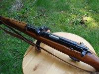
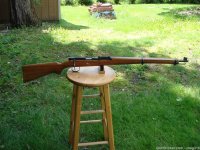
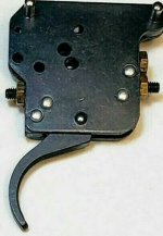
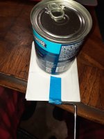
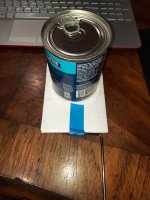
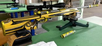
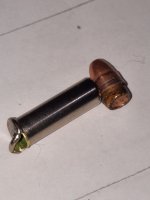
Id love to hang an Anschutz trigger off one like the photo below. I think he lives in Australia too.
She is a pretty gun and I don't have a rear lug gun in my collection yet.

I'm happy to help in any way That I can, McMaster Carr is an Industrial hardware supplier. I would start my search
with those words in the title for stuff near you. I will poke around later today for you ....

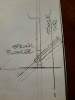
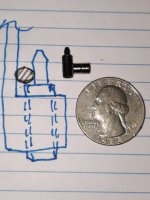
As for the spring plunger, the heavier spring plunger counter acts more trigger spring force. If you want a heavier trigger
you need a lighter plunger. OR, see the better M4 option below.

Fearless.... you almost got me.... You mentioned an #8-32, you don't want that yet.
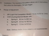
My 11 ounce trigger was achieved with the #6-32 plunger #8495A11 ... 1.5pounds / 4.5 pounds. ( With nylon locker ) $4.56 USD.
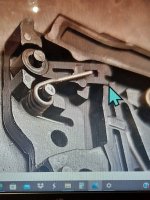
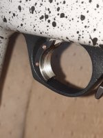
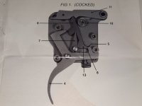
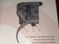
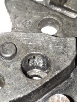
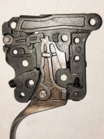
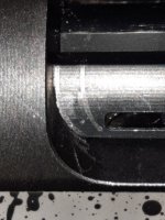
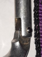
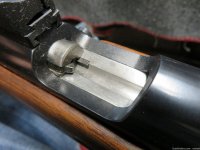
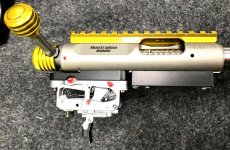
It also required the removal of the M4 spring adjuster in the front lower corner of the trigger housing. Photo #5

The next lighter long nose spring plunger would be #6-32 #8495A12.... 1 pound / 1.6 pounds. That would give you a heavier trigger.
But I don't think it would go low enough for you ?? 
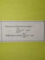
The number in blue is a shot in the dark but 57.4 oz. is likely it's low end
trigger weight with the #8495A12 installed.
The blue value is a very rough guess!! See rough examples in next paragraphs.

With the A11 installed I get an 11 ounce trigger pull. That plunger has a spring force of 4.5 pounds or 72 ounces.
If I add the 11 ounces that is required to pull the trigger I end up with 83 ounces total. Lets call the Factory force 83 oz.
The counter balance plunger is 72 oz. That means I need 11 ounces from my finger to fire the rifle.

The A12 plunger has a force of 25.6 ounces. If I subtract that from the 83 oz. factory spring force, I end up with a trigger
pull of 57.4 oz.

The above is a quick story that neglects a lot of detail and is only to convey an idea. The numbers are used to help people follow
the train of thought. I wish I would have tried the lighter plunger so that I could give you real numbers.....


you should get the #6-32 plunger with locker # 8495A11 ( 1.5-45 pounds ) I know, that is lighter than you want .
That's OK ..... we can fix it !!


That will provide you with two things:
It will incorporate an adjustable sear feature. Advance till FP release's and then out 110*. Approx. .023 sear engagement.
Your trigger will have a pull weight of 11 ounces. That value is not variable with the position of the set screw.
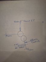
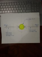
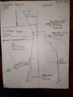
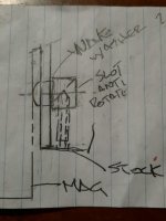
The factory has a spring adjuster located in the front lower corner shown in photo #5. It's the special black M4 screw.
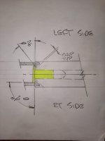
It's my belief that it retains the free end of the torsion spring with the housing as shown in the sketch.

That M4 screw can be used to overcome some of the 4.5 pound plunger force. It only needs to be totally backed off of the
spring if you desire an 11 ounce trigger pull. It can stay in the housing to keep it from getting lost.

In short, you will drill and tap for the #6-32 plunger and then install. Then set your desired sear engagement.
Then advance the front M4 screw to increase the trigger weight to your desired pull. Simple??


The #8-32 or M4 should be a back up plan incase you were to screw up the #6 or you wanted to experiment with the lightest
possible trigger for the B14R . The primary reason being that the #8 nicks the safety ball detent spring.
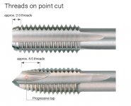
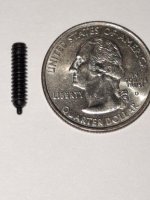
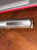
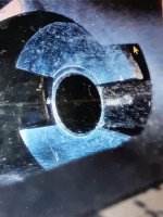
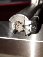
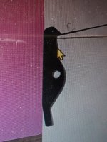
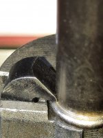
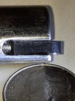
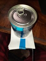
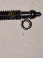
Photo #4 shows a spring plunger with the threads removed to clear the spring. The #8 has a 7.3 spring force and is
therefor too heavy.
If used, the M4 screw must be used keep the trigger force balanced. Slightly bias in the triggers favor....

In any case, the factory spring must always over power the spring plunger to some degree or the trigger wont reset.
If the #8 or M4 were to be used, the same front M4 set screw would be used to offset some of the 116.8 oz. plunger force.

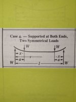
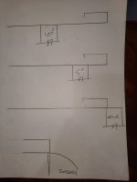
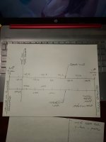
The trigger, in simple terms is basically a teeter totter. Sure...the pieces aren't straight lines but things need to be in
equilibrium.

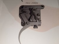
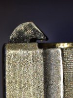
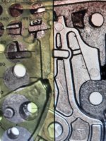
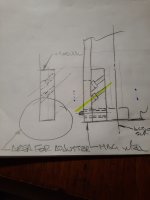
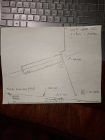
I have reposted the last two sketches for you. The trigger and upper sear are more for detailed information. The drawing is
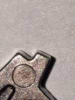
exaggerated to demonstrate how the parts interact. I feel that "Rounded Sears" is important enough to warrant
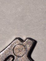
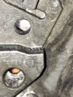
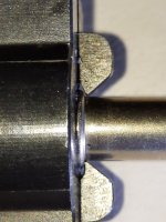
explain it again. If you zoom up on B14R trigger blade, you will see the rounded edges of the sear. They are not sharp and crisp.
Look at the sketch labeled "Rounded Sears" you will see what I believe is allowing some people to get a lower trigger weight
with the addition of only a set screw. There is a spring force on the lower circle ( sear ). There is a downward force on the upper
sear from the firing pin assembly. It has line contact with the upper circle ( sear )

In the prior post about friction, #138, we know that friction is independent of surface area contact. These two sears have very little
surface contact but but all of the forces are focused on the line contact that they share. Surface area goes down / unit pressure goes up.
I think that the only thing keeping the sub 16 ounce, #4-40 set screw guns from going off is friction and not sear overlap.
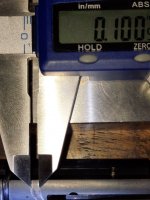
My best estimate from zooming up on the sears by a factor of 20 is that the radii are about .005"

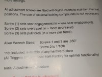
1"/ 32 tpi. = .03125" pitch / 360* = .000086806 per * of rotation x 2.5 trigger ratio = .000217014". Sear movement for 1*degree of rotation.
Keep in mind that at 110* backed off from the fired position, you will be contacting on sear flats like you should be.
110* X .000217014" = .02387" approximate sear overlap.

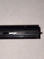
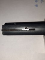
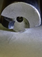
There is a window to view your sear in your trigger as well.

Magpie Bird,
""thought to rank among the world's most intelligent creatures, and is one of the few non-mammal species able to recognize itself in a mirror test.""
 

Attachments

  • 101A WITH ANS TRIGGER.jpg
    101A WITH ANS TRIGGER.jpg
    154.5 KB · Views: 70
  • ROUNDED SEARS AND #4-40 SET SCREW.jpg
    ROUNDED SEARS AND #4-40 SET SCREW.jpg
    260.8 KB · Views: 65
  • B14R TRIGGER BLADE SEAR ON SLIGHT ANGLE.jpg
    B14R TRIGGER BLADE SEAR ON SLIGHT ANGLE.jpg
    376.2 KB · Views: 58
  • TRIGGER AND UPPER SEAR SHOWING SEAR RISE PRIOR TO GOING OVER CENTER.jpg
    TRIGGER AND UPPER SEAR SHOWING SEAR RISE PRIOR TO GOING OVER CENTER.jpg
    272 KB · Views: 62
  • 20211108_072645.jpg
    20211108_072645.jpg
    394.5 KB · Views: 56
  • COCKED MAXIMUM SEAR ENGAGMENT LIMITED BY TRIGGER AND SHORT LEVER.jpg
    COCKED MAXIMUM SEAR ENGAGMENT LIMITED BY TRIGGER AND SHORT LEVER.jpg
    490.2 KB · Views: 60
  • #8-32 PLUNGER DOG BONED FOR SAFETY SPRING CLEARANCE.jpg
    #8-32 PLUNGER DOG BONED FOR SAFETY SPRING CLEARANCE.jpg
    293.3 KB · Views: 60
  • B14R TRIGGER TAPS AND PLUNGER McMASTER CARR #8495A11 with locker.jpg
    B14R TRIGGER TAPS AND PLUNGER McMASTER CARR #8495A11 with locker.jpg
    403.8 KB · Views: 73
  • 101A WITH ANS TRIGGER AND HANGER.jpg
    101A WITH ANS TRIGGER AND HANGER.jpg
    144.4 KB · Views: 70
They say the devil is in the details. It's a good thing these are small ones.....

I'm sure I had said that I felt the B14R was really nice rifle and any deficiency's it had were small details. The issues that I hear most is
FTE unfired rounds and FTF.

The extractor bellow is from a 1957 mdl . 54 Anschutz. The extractor has sharp edges, it's contoured around the case and it's inside corner
is undercut. Bergara could easily update their existing design to a similar profile. I applied side force to the bullet nose until it failed. It tore the
case base off rather than loss it's hold. I find it hard to believe that those small revisions wouldn't solve the FTE unfired bullet issue.

If I were Bergara, I would have one guy spend half day and regrind an existing extractor and find out. If I were a smith
working on your BR rifle I would do it. Youd need a vice, diamond tip wheel dresser and a modicum of skill.
A small surface grinder would make all of those changes. I checked the Anschutz spring and it feels no stiffer than the
B14Rs so that could be left as is.

I would like to work on the mag problem but my gun runs flawlessly. Do people have feed issues with the gun in the B14R
in the factory stock or is it restricted to aftermarket equipment?

I find your observation of the ejector location / bolt throw interesting. I have a new Anschutz 64 1903 that exabits the same behavior
and could be resolved in the same way. It's such a PITA that I rarely shoot it. If I still had a shop available, I would have fixed it
long ago. Other that it is a really fine rifle. That said, I should look into a simple fix for it.

I don't know what it would take to shorten the stroke by 1/4" but revising the ejector would be a snap. It just needs a longer tail.

I bought a Jewell HVR for the B14R, and it feels wonderful. No issues of any kind. It came set to 1 pound and I installed the lightest
spring they offered. That change lowered it to 4 ounces. No other adjustments were made. They claim it could go down to
1.5 ounces depending on FP down force.

I had put my Trigger Tech Diamond in my rifle too. It also went off without a hitch.

/////////////

Lots of interesting content in this thread.

The BR14 is close to being a really great rifle but certainly reliability needs to be improved.

In a straight up side by side accuracy test, we found the B14 was surprisingly more accurate at 100 yards than two Vudoos a RimX an Anshutzt 54 and a CZ452. Not by much mind you but it won the overall consistently.

As for reliability however it was the worst of the lot. Well next to RimX (Which also has a fatal reliability flaw)

That ejector post on the B14R behind the mag well caught brass and prevented forward bolt motion. At the manufacturer level this is an easy fix, but not so easy for the end user. If the bolt throw was shorter, the gap could be reduced to less than the width of a piece of 22 brass, or the ejector could be made longer to the rear to close out the gap.

The worst was when a live round would get jammed on the left side of the action and wedged into place in the lug way by moving the bolt forward. That gap needs to be either filled in or cleared away so a round will not hang up in there.

As for feed issues, we did make improvements using tape, but the most notable improvement we made was the addition of a jack screw on top of the rear dead part of the mag. That screw was used to control how high up the mag could be pressed.

In our case the B14R was fitted in an MPA chassis so we could control the mag latch, but the balance could only be achieved by trapping the mag between the jack screw on top and the latch on the bottom. Without the jack screw the mag is subject to too much vertical movement to feed reliably.

It did run with both Bergara and Vudoo plastic mags with this modification.

Due to the above, the rifle was replaced by a Vudoo V22 primarily for the reliability, but also for a longer and heavier barrel to improve balance for PRS style shooting.
 

Attachments

  • ANS 57 LATERAL LOAD APPLIED AT BULLET.jpg
    ANS 57 LATERAL LOAD APPLIED AT BULLET.jpg
    245.7 KB · Views: 52
  • ANS 57 EX NO CASE UNDER CUT TO CLEAR CASE RADII.jpg
    ANS 57 EX NO CASE UNDER CUT TO CLEAR CASE RADII.jpg
    580.3 KB · Views: 52
  • ANS 57 EX 3 BEST VIEW.jpg
    ANS 57 EX 3 BEST VIEW.jpg
    396.4 KB · Views: 49
  • ANSCHUTZ 57 ROUNDED TIP BY CASE WALL.jpg
    ANSCHUTZ 57 ROUNDED TIP BY CASE WALL.jpg
    355 KB · Views: 51
  • Like
Reactions: PracticalTactical
To my mind, this entire thread, this entire forum is a place for people to get together and talk about issues. concerns
and solutions, etc.

When I read a problem, I try and give people my best advice along with information to support my
position. Because I said so doesn't work with adults. I welcome and expect people to question my data. They should!

In post #131 I said that I would look into getting getting documentation on Friction. I added it to my simple explanation.
My simplified explanation does nothing to make me appear smart, it is for people that have trouble with math. I don't
subscribe to baffling people with BS. I sincerely want them to be able to make an informed decision.
The documentation doesn't make me look intelligent either.... It belongs to someone else. My greatest input
was to find the simplest version of it for general consumption.

100 pounds on a 10 x 10 plate has 1 pound per square in load. 100 pounds on a 10 x 5 plate has 2 pound per square inch load.
So friction is independent of surface area. Then I find the best, clearest, simplest information on the internet that I can
to support my example. All of my sketches, posts and searching on the net takes time and effort on my part.
It is all done in the hopes of helping other people make the best decision possible.

You'll have to forgive me, it was late and I missed this detail at 1:30 this morning....

You said...."There's not a single thing in this thread I would do except maybe shim magazines"

That virtually translates into, all of the information in this thread is stupid and has no merit whatsoever!!
That implies all of the contributors are stupid.

But you think that shimming your mag with tape is the appropriate resolution to the FTF problem.


I don't have any FTF problems but If I did my solution would be well thought out and executed. I don't expect you to
understand the sketches below, not bc your stupid but because they are crude and only one view.

There is a wave spring washer. The button has an angled slot in it that pushes the button in or out of the mag well
when the set screw is rotated.
The button has a slot in it to prevent it from rotating. The set screw is a 1/4-20 and has a pitch of .050"
1"/ 20=.050".... divide that by 360* = .000138889. If you rotate the set screw by 45* the button will move by .00625"

It's a cute sketch.... It cant really work as is bc it cant be machined or assembled. Only the function is solid.

The second one is a module approach and that would ease many machining and assembly problems.
It's still requires too much work.....

The third and likely the best is the spring plunger. It's angle would allow for easy machining of the tapped hole directly
into the stock.
The plunger nose would just push out of the way during mag insertion.
1/4-20 #3126A26 or one like it. (4 options) OR better still is the M6 8281A25... it has 6 nose force options and an Acetal nose.

I'm surprised that you expected everyone to stay silent and give you a perfunctory smile because you included an LOL in your
assertion that we are all ignorant brainless fools? LOL is often inserted so the poster has a way out of her comment.
Just kidding LoL !!

Since you seem to feel we are off track, why don't you straighten us out with some of your wisdom. Contribute
to this thread and forum in a positive way so that we may see our shortcomings and correct them.
When people know better, they do better. Don't be a an un mensch, help us out wont you?


Your welcome to start with me and my idiotic notions about friction and surface area. What was I thinking?
Anyone can stand back and criticize and add nothing positive to the conversation.

btw... your the only person that I have called out on their ""opinion.""

Signed
Shawn Drivel Carroll
I wonder if I'm also the only person you ever threatened. That was a threat right? Isn't that why you edited it out. You wrote that I "came dangerously close to calling you stupid." I wonder why you wrote dangerously. Are you going track me down and kill me?

My post meant exactly what I wrote; nothing more. My gun works, why would I "fix" it? If you want to interpret my joke as something other than a joke, that's your issue not mine.

As for calling people stupid, you called a whole lot of people stupid for shimming mags.

BTW. As of right now, you are the first person that I "Ignore."
 
Not an issue to report exactly . . .

I haven't had any trouble or complaints with my trigger, but I did some modifications to another identical trigger and decided to remove the original and do some testing on the modified one. Much longer report on the modifications and testing when I've got it working.

But in the meantime, I read somewhere about somebody flushing their new Jewel trigger and getting some production chips and gunk out of it so first I flushed my modified trigger (Mineral Spirits) and got a BUNCH of chips out of it - no doubt most from the drilling and taping.

Today I flushed the original and washed a few metal chips out of it too. Enough that I deem it a worthwhile exercise - likely worth all of the 25 cents worth of Mineral Spirits. I'm not expecting any improvement (or degradation) in operation, but imagine that clearing out any junk might keep parts from grinding and may preserve if not extend the life of the trigger.
 
Took the Bergara B14 out today and shot one of 25 shot targets that I bought from Killough sports. The Bergara now sits in the JV Element 4.0 chassis. Feeds well but the mags rock back and forth side to side. Wind today was 13 mph so had to deal with that. This was my target at 50 yards with SK standard. I know I can do better and the rifle can as well. Pulled a few. First time shooting one of these targets. Fun to shoot.

6BDB21FF-161C-4B45-BECA-3741B27FF2A9.jpeg
 
Dan,

Have you had any trouble with the safety function after your mod?

I was asked how it could work if the spring force diminishes as the trigger gets pulled. It does reduce....

I made a graphic to illustrate the spring force reduction as the plunger point moves off it's stop position.

I added a #6-32 plunger to my trigger. It has a final force of 72 ounces. I backed the plunger out about 110* after
the firing pin dropped. That should have provided me with a sear engagement of about .024".
There is a 2.5 : 1 ratio within the trigger so to get a sear of .024", the plunger needs to move about .0096"
( 1 / 2.5 = .4 ) ( .024" x .4 = .0096" )
Moving .009" off of the sear stop reduces the spring force by about 7.2 ounces.
The point was, you don't loose much force in the small distance traveled to disengage the sears.


Not an issue to report exactly . . .

I haven't had any trouble or complaints with my trigger, but I did some modifications to another identical trigger and decided to remove the original and do some testing on the modified one. Much longer report on the modifications and testing when I've got it working.

But in the meantime, I read somewhere about somebody flushing their new Jewel trigger and getting some production chips and gunk out of it so first I flushed my modified trigger (Mineral Spirits) and got a BUNCH of chips out of it - no doubt most from the drilling and taping.

Today I flushed the original and washed a few metal chips out of it too. Enough that I deem it a worthwhile exercise - likely worth all of the 25 cents worth of Mineral Spirits. I'm not expecting any improvement (or degradation) in operation, but imagine that clearing out any junk might keep parts from grinding and may preserve if not extend the life of the trigger.
 

Attachments

  • 2 FORCE AND DISTANCE SCALE.jpg
    2 FORCE AND DISTANCE SCALE.jpg
    253.3 KB · Views: 54
  • 1 RATIO AND PIVOT POINTS LABLED. 2.5 TO 1 OR 40%.jpg
    1 RATIO AND PIVOT POINTS LABLED. 2.5 TO 1 OR 40%.jpg
    341.1 KB · Views: 58
Dan,

Have you had any trouble with the safety function after your mod?

I was asked how it could work if the spring force diminishes as the trigger gets pulled. It does reduce....

I made a graphic to illustrate the spring force reduction as the plunger point moves off it's stop position.

I added a #6-32 plunger to my trigger. It has a final force of 72 ounces. I backed the plunger out about 110* after
the firing pin dropped. That should have provided me with a sear engagement of about .024".
There is a 2.5 : 1 ratio within the trigger so to get a sear of .024", the plunger needs to move about .0096"
( 1 / 2.5 = .4 ) ( .024" x .4 = .0096" )
Moving .009" off of the sear stop reduces the spring force by about 7.2 ounces.
The point was, you don't loose much force in the small distance traveled to disengage the sears.

As it turns out, the #6-32 long nose spring plunger can also be bought on Evil Bay. #232437784081
It's a Carr Lane CL-10-SPS-16-32 X 17/32 Spring Plunger Heavy. With locking element. 1.5 pound initial - 4.5 pound
final force. $4.61 each.


Not an issue to report exactly . . .

I haven't had any trouble or complaints with my trigger, but I did some modifications to another identical trigger and decided to remove the original and do some testing on the modified one. Much longer report on the modifications and testing when I've got it working.

But in the meantime, I read somewhere about somebody flushing their new Jewel trigger and getting some production chips and gunk out of it so first I flushed my modified trigger (Mineral Spirits) and got a BUNCH of chips out of it - no doubt most from the drilling and taping.

Today I flushed the original and washed a few metal chips out of it too. Enough that I deem it a worthwhile exercise - likely worth all of the 25 cents worth of Mineral Spirits. I'm not expecting any improvement (or degradation) in operation, but imagine that clearing out any junk might keep parts from grinding and may preserve if not extend the life of the trigger.
 
Shawn: No luck getting time to work on the trigger this week - BUT - for the benefit of the folks that haven't been part of our private messages --

I ran the #6-32 spring-plunger screw in until the trigger dropped and the backed it out about 120 to 135* but after recocking the safety was stuck. While it "should't be" it seems the screw is interfering with the safety. If I back the screw out far enough to free up the safety my trigger pull is about 20-24 oz BUT several times I would get trigger fall just working the safety lever, so pretty unsafe.

Basically I could get a trigger fall almost any time the screw was in contact with the trigger with a few operations of the safety.

Without any adjustment screw - back, front, or bottom - the trigger pull is about 2.75 lbs/44 oz. And no amount of manipulation of the safety causes the trigger to fall.

Has anybody else tried the #6-32 screw? If so - what has been your experience??

My current plan - hopefully I'll get time this weekend - is to take a stab at the dog bone fix mentioned elsewhere with regard to the #8 screw - filing some of the threads off the section of the screw that might interfere with the safety spring.

We'll see . . .

Best thing though - I can always just revert back to the original trigger without these extra adjustment screws. Actually, in that case I might just drop in the TriggerTech Special from my Remington 700 and put the Bergara trigger in the Remington since the 308 is NOT getting much use these days!
 
DFCE0FA5-EEE9-47F1-91BC-9EE474A049A8.jpeg
I must be lucky, I haven’t had any problems at all and I doubt I will. But that’s just me. I bought a barrelled action and dropped in a MDT XRS chassis with the upgraded forend. Haven’t had any miss fire or ejector issues. It does have a hard bolt close. My only complaint about it but I feel like it may soften up. I have about 500 rounds through it now and 1 match with it. I did buy a handle and bolt knob from anarchy outdoors (through go big tactical here in Canada) and the hard bolt close is easier now with the longer knob etc.
 
  • Like
Reactions: DubfromGA