Very nice! Looks greatJust finished mine up today. Many Thanks to some of the hide members for helping me out with my questions through PM’s.
Went with a 36v 16.7a power supply that is running the ZVS board only. I currently have to 36v PS adjusted to the max at 42v. Might tinker with the voltage later. I have a separate 12v 5a power supply running all other components, timer, fans, coolant pump, etc.
The coil is 1/8” OD copper tubing with 8 windings soldered to 1/4” tubing. Diameter is roughly 7/8” and it is 1-1/4” tall.
I made a few different coils with the same diameter but more or less windings to see what it would do. I settled on the current one because the neck on a 308 will have a faint glow at 4.5 secs. Tempilaq will be in later today and then I can fine tune it.
Currently it is peaking out at 7.3-7.4 amps and 310 watts when annealing a case. Seems low when compared to others. Checked for the normal issues but found nothing. It must be the way I have it set up....but it works.
View attachment 7873616
View attachment 7873617
View attachment 7873618
View attachment 7873619
View attachment 7873620View attachment 7873621
View attachment 7873622
View attachment 7873623
View attachment 7873624
Join the Hide community
Get access to live stream, lessons, the post exchange, and chat with other snipers.
Register
Download Gravity Ballistics
Get help to accurately calculate and scope your sniper rifle using real shooting data.

Install the app
How to install the app on iOS
Follow along with the video below to see how to install our site as a web app on your home screen.
Note: This feature may not be available in some browsers.
You are using an out of date browser. It may not display this or other websites correctly.
You should upgrade or use an alternative browser.
You should upgrade or use an alternative browser.
Homemade Induction Annealer
- Thread starter TSloper
- Start date
This is sort of a side note to these home built induction annealers - I bought a “Hot Rod” induction heating tool for car repair (it’s made for heating stuck bolts & nuts) with the side thought of building a setup to use it for annealing as well. It does come with three different size coils, so I tried the smallest for annealing.
To my surprise, it’s pretty slow to heat up brass; it’ll turn a 1/2” steel bolt red hot in about the same time it takes to anneal a single 308 case, as verified with Tempilaq. I’m guessing something to do with frequency maybe? It seems well tuned for steel bolts but inadequate for brass, despite the much lower mass of the brass case neck.
Any thoughts on that from you guys who know this stuff? I can do wizardry with engines or machining but only know just enough about electronics to let the smoke out. Not planning on modifying the Hot Rod, but it’d be useful to understand why it doesn’t work as well, if you guys know.
To my surprise, it’s pretty slow to heat up brass; it’ll turn a 1/2” steel bolt red hot in about the same time it takes to anneal a single 308 case, as verified with Tempilaq. I’m guessing something to do with frequency maybe? It seems well tuned for steel bolts but inadequate for brass, despite the much lower mass of the brass case neck.
Any thoughts on that from you guys who know this stuff? I can do wizardry with engines or machining but only know just enough about electronics to let the smoke out.
Not planning on modifying the Hot Rod, but it’d be useful to understand why it doesn’t work as well, if you guys know.Looks great, just order the case. Can you PM a parts list? I have the mgnz board, but I do not see it on your build. I am guessing it is under the mother board tray.Thanks Dragonetti. It’s a Cool Master - Master Box Q500L. When I first got it, I thought I wouldn’t be able to fit everything in there. But I made it work.
Looks great, just order the case. Can you PM a parts list? I have the mgnz board, but I do not see it on your build. I am guessing it is under the mother board tray.
No problem. Give me just a bit to get the parts list together. Currently at work, but I’ll post it hopefully this evening. I did not us the MGNZ board on this build. Been debating on changing to it later down the road. Wanted to keep it simple starting off to make sure I could get it to work. So far so good.
Ran a test batch earlier this morning using Tempilaq 750. Think I might keep it somewhere between 4.2 & 4.4 secs.
The last picture of the three cases are out of my good batch of 308 Lapua at 4.3 secs.
What brand of brass did you use for the timer test?
Just remember that all brands are not created equal...the time for Hornady brass will probably differ from Lapua for an optimal anneal. Different brass composition, different wall thickness, etc. will affect the time required.
But at the same time, the temperature range that gives an acceptable result is just that, a range...so one timer setting can work for different brands, it just may not be optimized...
So here is the parts list for anyone who wishes to use it. As you can see; its not much different from the common parts that everyone is running already. Keep in mind that some parts I made are from materials on hand here at the office and made on a lathe. As mentioned in my previous post; I may incorporate a MGNZ board later down the road and add a display to make it purdy...but haven't decided to do it just yet. I've leaned from other project that if it works good in the beginning...leave it alone and if its not broke, don't fix it. BUT.....there's always room for improvement LOL.
Case: Cool Master Master Box Q550L
https://www.amazon.com/gp/aw/d/B07Q8VJ17J?psc=1&ref=ppx_pop_mob_b_asin_title
ZVS Board:
https://www.amazon.com/gp/aw/d/B0827C3J2K?psc=1&ref=ppx_pop_mob_b_asin_title
SSR Relay:
https://www.amazon.com/gp/aw/d/B079BGGVYX?psc=1&ref=ppx_pop_mob_b_asin_title
Timer Relay:
https://www.amazon.com/gp/aw/d/B07VLXR7Z1?psc=1&ref=ppx_pop_mob_b_asin_title
Volt/AMP Meter:
https://www.amazon.com/gp/aw/d/B013PKYILS?psc=1&ref=ppx_pop_mob_b_asin_title
12V-DC Power Supply (use this to run all fans, pump, etc only)
Amazon product ASIN B078RY6YY3
36V-DC Power Supply (use this to run the ZVS board only - this power supply can be substituted for user preference)
https://www.amazon.com/gp/aw/d/B079D7H2L1?psc=1&ref=ppx_pop_mob_b_asin_title
Coolant Pump:
https://www.amazon.com/gp/aw/d/B01CJJFOIW?psc=1&ref=ppx_pop_mob_b_asin_title
Coolant Radiator:
https://www.amazon.com/gp/aw/d/B07XP3WR5Q?psc=1&ref=ppx_pop_mob_b_asin_title
Fans:
https://www.amazon.com/gp/aw/d/B07PFBKD4J?psc=1&ref=ppx_pop_mob_b_asin_title
1/8" OD Copper Tubing:
https://www.amazon.com/gp/aw/d/B07QDL1J7W?psc=1&ref=ppx_pop_mob_b_asin_title
5/32" OD - 1/8" ID Copper Tubing:
https://www.amazon.com/gp/aw/d/B07QFP2YHX?psc=1&ref=ppx_pop_mob_b_asin_title
Power Terminal Strip: ( I used one that I here at the office, but this one will work)
Amazon product ASIN B01F47OZZE
Parts that were made by me are....The holder for the voltage meter shunt, mounting block for the SSR Relay, mounting table for the ZVS board (PTFE, ABS, or any type of plastic will work and keep these insulated from the steel case). The bullet case pilot and pilot holder.
DO NOT use the PSU bracket that comes with the Cool Master case for the ZVS board. I found out the hard way and fried my SSR and ZVS board on the first run even though I had plastic insulators on it. Also keep an eye on what screws you use to mount the ZVS board and make sure the heads are not too large. One of the heads on one of the screws was touching the heat sink on the ZVS board (didn't notice it) and I had it mounted to the metal bracket (that come with the Cool Master case) creating a short that sent my ZVS board into total runaway status....sucker got hot quick and poof!
So far as clear tubing and brass fittings for the cooling system; bought these from my local hardware store. Best to take it and test fit everything while at the store. Nylon spacers and screws can be used and purchased from your local hardware store as well.
I chose to use the 1/8" OD copper tubing for my build since it gave me good results. Best to experiment with different coils as mentioned throughout this thread and fine tune to your preference.
I'll edit if I forgot anything....thought I would put up a quick list during lunch break.
Last edited:

What brand of brass did you use for the timer test?
Just remember that all brands are not created equal...the time for Hornady brass will probably differ from Lapua for an optimal anneal. Different brass composition, different wall thickness, etc. will affect the time required.
But at the same time, the temperature range that gives an acceptable result is just that, a range...so one timer setting can work for different brands, it just may not be optimized...
The test cases with Tempilaq are Lapua as well.
My wife bought me a 3d printer for my birthday, so I made a little bezel for my LCD display. Looks much better than just having it hanging out in the open.

I've also got to do a bit of rewiring, I got a shock while using it the other day and found that my ground wire had become disconnected. I have ordered a receptacle for a PC power cord that I can mount at the back of the case, this should be a bit more professional than just tying a knot in the power cord so that it can't pull out. And I won't be putting any strain on my power connections whenever I move the power cord either.
Kristian
I ran a batch of 50 cases on it this morning to see how it would performed on a somewhat large batch. The only issue I encountered was every now and then the amps and watts would spike to the low 12A / low 500W range. During previous testing it would only peak at 8.2-8.5A at 310-330W. This only happened on about 8-10 cases. Wonder why that happened? The rest of batch was at the lower amps and watts stated above.
Checked everything....wiring, coil not touching, etc. The case was seated in the pilot the same every time so case height in the coil can’t be the issue. Any thoughts? Open to suggestions.
The only thing that I can think that might be causing it is I placed a temp probe within the ZVS capacitor bank to monitor the temp. I wanted to make sure that I placed it to where it is not completely between the coils leads. I also wanted to make sure that I placed the probe wire away from the coil. Could it still be too close to the coil and leads? Max temp hit 144F but cooled down pretty quick once the batch was done.
Other than that, the batch turned out good. The cases that hit the 12A/500W range looked the same as the rest.
Update....
Ran another test on 40 cases without the temp probe installed. It seems that the temp probe may have cause a little eddy's current being close to the leads. All cases tested were back in the range of 8.0-8.4A and the wattage stayed between 340-350 watts. Tampilaq on all the cases show that it is running pretty consistent at 4.5 secs for 308.
Ran another test on 40 cases without the temp probe installed. It seems that the temp probe may have cause a little eddy's current being close to the leads. All cases tested were back in the range of 8.0-8.4A and the wattage stayed between 340-350 watts. Tampilaq on all the cases show that it is running pretty consistent at 4.5 secs for 308.
I am currently in the middle of building/testing this wonderful inductive anealer based on the ZVS (Zero Voltage Switching) 100W board found on Amazon. A few tips (lessons learned the hard way):
1. Make certain that you switch your PS to 110 VAC (usually found on the side of the PS) if you live in the US, many units are shipped set to 220 VAC.
2. Get at least a 20A power supply if you are using a ZVS 1000W board. 12V to 48V is the recommended voltage range, higher voltages are recommended since they will speed up your annealing time; additionally, the MOSFETs will switch more effeciently and draw less current (a good thing).
3. ALWAYS have a work coil installed on the circuit when you turn it on. If you don't do this, the circuit will not resonate and one of your two MOSFETS will die a sudden and unnatural death.
4. DO NOT turn on the power supply if it is directly attached to the ZVS at startup - you need either a switch or timer with a relay. Start up the power supply, then connect (via a switch or timer) the ZVS board. Power supplies have rather slow startup output voltages which is fine for most circuits but not for a ZVS board. Some folks report a board that just doesn't work and this is usually the root cause (one of the two MOSFETs might be dead). The MOSFETs need a good kick at startup and that is the reason for the switch or timer.
5. Get an Ammeter, if you are drawing more than 20A on the ZVS board then this is not good, turn it off and start debugging. You should see between 4 to 6 Amps on the ammeter if you are using the supplied work coil. This work coil will not anneal brass but it will cause steel objects (like nails) to glow bright red. Remember, watch the ammeter, current draw increases as you place objects into the coil and you DO NOT want to let it get above 20A.
6. Insulate your coil (I use fiberglass tubing over my copper coil) the coil is carrying large amounts of current and if a conductive object comes into contact with the coil in 2 places, it can change the inductance of the coil (usually will lower it) and will cause your current (amps) to spike.
7. Use a seperate 20A relay or SSR (Solid State Relay) and use the switched output from the timer to drive the relay. The Relay is intended to allow large amounts of current from the Power Supply to the ZVS board.
8. The MOSFETs (devices attached to those large heatsinks) have no thermal conductive paste. This means that the MOSFET is retaining more heat and not transferring all that heat to the heat sink. Get some thermal paste for electronics and remove the phillips screw, gently bend the MOSFET and apply the thermal paste to the back side of the MOSFET. Gently bend the MOSFET back and install the phillips screw. Not an easy chore but your MOSFETs will thank you.
9. Highly recommend that you use a water cooling system, the work coil gets plenty hot.
Last edited:
So I'm following this thread for eduational purposes.
Seems like making one of these is a lot of trouble? and can't you get the same results using one of the torch models?
It's a lot like this:
They both get you to where you want to go.

People are trying to get AMP results without spending AMP money. You can anneal successfully with flame, but it is a much less consistent process.So I'm following this thread for eduational purposes.
Seems like making one of these is a lot of trouble? and can't you get the same results using one of the torch models?
wonder if they will ever have one running off the hot air expelled from leftists it would be like a nuclear reactor and need cooling towers lol
Nope. Not unless you’re comparing to hand holding a case and a torch. Otherwise your analogy is a massive exaggeration.Perhaps a better analogy... Measuring seating depth methods....


The induction thing is neat, and if that’s what you’re into building, cool. Tell yourself it’s better, even, if that’s what it takes. But be honest about it with everyone else.
Even for hand holding (the only way I've done it so far).. it's still an exaggeration. I withdraw the comment your honor. Just me trying to be funny.
Thanks Hardware.Thanks for all your patience with me.
Finally I found the reason! Now it is clear but I never thought about it before. On the photos you can see that I build a little aluminium block holding the thermo element I put in to be able to see the temperature of the Mosfet cooler. Well, that alone is maybe a good idea but not fixing the block to both Mosfet coolers!!! That was the short I couldn't find.
Now it is heating the brass in seconds - great!
You fixed my problem 1.5 years after you fixed yours. I had the same symptoms and would never guess that the heat shield was causing a short circuit. My heat shield touched the donor PC chassis metal frame occasionally. Learning from you fixed my problem
Where can I find insulation for the coil? I've been googling for hours......I am currently in the middle of building/testing this wonderful inductive anealer based on the ZVS (Zero Voltage Switching) 100W board found on Amazon. A few tips (lessons learned the hard way):
1. Make certain that you switch your PS to 110 VAC (usually found on the side of the PS) if you live in the US, many units are shipped set to 220 VAC.
2. Get at least a 20A power supply if you are using a ZVS 1000W board. 12V to 48V is the recommended voltage range, higher voltages are recommended since they will speed up your annealing time; additionally, the MOSFETs will switch more effeciently and draw less current (a good thing).
3. ALWAYS have a work coil installed on the circuit when you turn it on. If you don't do this, the circuit will not resonate and one of your two MOSFETS will die a sudden and unnatural death.
4. DO NOT turn on the power supply if it is directly attached to the ZVS at startup - you need either a switch or timer with a relay. Start up the power supply, then connect (via a switch or timer) the ZVS board. Power supplies have rather slow startup output voltages which is fine for most circuits but not for a ZVS board. Some folks report a board that just doesn't work and this is usually the root cause (one of the two MOSFETs might be dead). The MOSFETs need a good kick at startup and that is the reason for the switch or timer.
5. Get an Ammeter, if you are drawing more than 20A on the ZVS board then this is not good, turn it off and start debugging. You should see between 4 to 6 Amps on the ammeter if you are using the supplied work coil. This work coil will not anneal brass but it will cause steel objects (like nails) to glow bright red. Remember, watch the ammeter, current draw increases as you place objects into the coil and you DO NOT want to let it get above 20A.
6. Insulate your coil (I use fiberglass tubing over my copper coil) the coil is carrying large amounts of current and if a conductive object comes into contact with the coil in 2 places, it can change the inductance of the coil (usually will lower it) and will cause your current (amps) to spike.
7. Use a seperate 20A relay or SSR (Solid State Relay) and use the switched output from the timer to drive the relay. The Relay is intended to allow large amounts of current from the Power Supply to the ZVS board.
8. The MOSFETs (devices attached to those large heatsinks) have no thermal conductive paste. This means that the MOSFET is retaining more heat and not transferring all that heat to the heat sink. Get some thermal paste for electronics and remove the phillips screw, gently bend the MOSFET and apply the thermal paste to the back side of the MOSFET. Gently bend the MOSFET back and install the phillips screw. Not an easy chore but your MOSFETs will thank you.
9. Highly recommend that you use a water cooling system, the work coil gets plenty hot.
Google search 3mm basalt or fibreglass insulating sleeve. You'll find it on eBay or Amazon.Where can I find insulation for the coil? I've been googling for hours......
I'm on board now and about to order parts. I'm not interested in reinventing the wheel on this project. I'm looking for a straightforward build with parts list. It looks like JMD82 has done just that very nicely. Before I order parts I have a couple of questions for JMD82 or others.
1) I'm not understanding where the brass enters and exits the coil. It looks like it is dropped into the top and them would exit into the housing itself. I would like to build one with an auto bottom door dump. If so, do I need to orient the coil to another location? Maybe I have not read thoroughly enough. Could someone explain please.
2) Has anyone replicated this exact design with the parts list provided? If so, are there any mods or improvements?
I've seen several different methods of auto-case feeds/dumps.
I think there are only two real rules.
Be aware of high heat of the case on the materials, and don't let any metal get too close that will affect the area around the coils and/or heat up as well as the case.
Most designs I've seen have the coils outside of the housing. I've seen trap doors opened with electric pistons and large rotary circles with open holes to drop down. Design above looks like manual for both insert and removal on that shell holder.
Make sure the case isn't touching the sides of the coil when activated. The thermal insulation solves that I believe.
I see that several are using the Arduino board. That looks like a simple solution to me. It looks like the Arduino ($90 shipped to USA) adds about $77 more cost than a timer relay ($13). Other than additional cost, are there any other pros and cons to this board?
I used the MGNZ Arduino board for mine. It's set up pretty much plug and play with the software already loaded. The latest version has a stepper driver built into it to run a case feeder with a closed loop stepper and can run the case dropper using either a solenoid or a small RC car servo motor. There is a parts list and wiring instructions on Mark's website.I see that several are using the Arduino board. That looks like a simple solution to me. It looks like the Arduino ($90 shipped to USA) adds about $77 more cost than a timer relay ($13). Other than additional cost, are there any other pros and cons to this board?
I designed a stepper motor driven case feeder and a dropper setup and have uploaded both to thingiverse, if you have access to a 3d printer you can make them pretty easily or send the files to one of the online 3d printing shops and have them done. The files are free to download and use. Mine has done thousands of cases now and the parts do the job really well.
https://www.thingiverse.com/thing:4916236
https://www.thingiverse.com/thing:4902058
$90 seems steep. Here is a nano for $25 on Amazon.
Hmm.. Amazon links don't work. Just search Arduino Nano on the site.
For a timer and stepper motor, you could use a ESP32 just as well. $10 delivered.
https://www.ebay.com/itm/124835593994
Hmm.. Amazon links don't work. Just search Arduino Nano on the site.
For a timer and stepper motor, you could use a ESP32 just as well. $10 delivered.
https://www.ebay.com/itm/124835593994
The $90 is based on the MGNZ board $67.50 plus international shipping $21.95. This looks like a good choice but due to extra cost and shipping time I have decided to do differently.$90 seems steep. Here is a nano for $25 on Amazon.
Hmm.. Amazon links don't work. Just search Arduino Nano on the site.
I have ordered parts largely based on the list on post #557 above. I have gone with a 48V power supply. I couldn't get the 1000V but went with 800V.
Question on the ammeter. I ordered the same one in post #557.
Amazon product ASIN B013PKYILS
1) Do I wire the shunt in the negative lead?
2) Do I supply power to the ammeter from 48V or 12V?
Yes, it says to wire on negative side of the load. The Amazon has a wiring diagram.
Wire to the 48V so you can see the actual voltage running the ZFS board. It can handle 6V-100V.
Wire to the 48V so you can see the actual voltage running the ZFS board. It can handle 6V-100V.
Certainly, the shunt goes in between the 48V power supply and the ZFS, but do I supply power to the ammeter display from the 48V also. Don't want to fry it right off the bat.Wire to the 48V so you can see the actual voltage running the ZFS board. It can handle 6V-100V.
The $90 is based on the MGNZ board $67.50 plus international shipping $21.95. This looks like a good choice but due to extra cost and shipping time I have decided to do differently.
I have ordered parts largely based on the list on post #557 above. I have gone with a 48V power supply. I couldn't get the 1000V but went with 800V.
Question on the ammeter. I ordered the same one in post #557.
Amazon product ASIN B013PKYILS
1) Do I wire the shunt in the negative lead?
2) Do I supply power to the ammeter from 48V or 12V?
When you get it you'll see the wiring diagram on the back. It will wire directly into the + and - of the 48v supply, and then 2 more terminals for the + and - of the load itself. It will turn on with the supply and continually monitors voltage and current.
I'm wanting to tie a momentary button in between the timer and the relay for the ZFS. This will serve as a "manual" control. Will the 12v back feed into the timer (when button is activated) cause any damage to the timer?
That's what happened to me. I ended up putting a SSR in. I burned up a couple timers until I figured that out.I'm wanting to tie a momentary button in between the timer and the relay for the ZFS. This will serve as a "manual" control. Will the 12v back feed into the timer (when button is activated) cause any damage to the timer?
If you are going the Arduino route, you just use one of the other I/O ports for the button and update the code to activate the relay.
Not sure you need SSR, but an optocoupler isolated relay may work as well. $12 for 30A relay on amazon.
Not sure you need SSR, but an optocoupler isolated relay may work as well. $12 for 30A relay on amazon.
So, if the timer has a "normally open" relay built in it should be safe. But if not, I will need to tie in another relay/ssr between the manual button and the timer. This will insure an open status and couldn't back feed. Right?That's what happened to me. I ended up putting a SSR in. I burned up a couple timers until I figured that out.
I held up on the MGNZ Arduino for now. It may come back into play as I add case feeder and case drop. Timer only for startup.If you are going the Arduino route, you just use one of the other I/O ports for the button and update the code to activate the relay.
Not sure you need SSR, but an optocoupler isolated relay may work as well. $12 for 30A relay on amazon.
What I'm understanding now is that I do need something in between the timer and button to create an open circuit to protect the timer. Is this the consensus?
How about adding a diode between the timer and button? My very limited understanding is this is like a "check valve" and would only allow current in one direction. Maybe this one.
Amazon product ASIN B06XB1R2NK
Last edited:
I'm curious how Dbspaded7 wired his up that caused the problem.. if it was the 6v-30v setup which I would expect a potential feedback issue from the board. You are using higher voltage (48) so you'd need to use the second wiring setup. That setup may not have that issue.
Either way, you may be able to protect the feedback issue with a diode next to the timer.
Either way, you may be able to protect the feedback issue with a diode next to the timer.
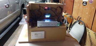
Trying to remember. Originally I had it wired power supply- momentary switch-timer- zvs board. Also have a ammeter in there too. It fried a couple timers. I put in the solid state relay. It fixed my problem. I have annealed a thousand or so pieces of brass since and it works great. Since I have the ssr my anneal times are like a second or so longer than my brothers. He didn't do an SSR. I was getting feedback and cooking timers and he didnt have that problem. Not sure why I was. I just got tired of troubleshooting and buying timers. Could have been a bad zvs board too. I ended up buying another zvs board as well. That could have been the problem from the get go. I am definitely not an expert but this is what I did. Here is my annealer. If I could do it over I would definitely make it smaller. My build was with a 36v power supply. I just used step down voltage regulators to run my fans, water pump, and solenoid(case drop)
Attachments
Halffull Sorry for not responding. I built mine to mimic the AMP annealer.
I don’t do mass quantities, so I did not see a need for doing an auto feed or drop system. Each case is loaded into the top via shell holder and when it is done, I just pull the shell holder and case out. I imagine you could incorporate an auto feed and drop system into my design, but you will more than likely need to build some type of platform to raise the unit up so cases can fall into a pan from the bottom. Also; when I insert my cases, they are upside down…case mouth and neck in downward position. If you want to add a drop shelf like the one mentioned in post 578, I imagine you can. The cases would then need to drop in, in the upward position with case mouth and neck facing upwards. The case feeder can be mounted to the top panel to drop the cases into the coil. You could also mount the coil, case feeder, and drop shelf on the outside of the housing…it’s all a matter of preference.
I made a few changes to mine since my last post. I added a led momentary push button to trigger the timer and changed my volt/amp meter. The volt/amp meter I’m currently running can monitor voltage, amps, watts, and temp. The timer relay is the original one have listed and is powered by a 12v PS. All fans, timer, relays, coolant pump are powered by the 12v PS. The only components using the 36v PS is the ZVS board and I believe the volt/amp meter…I will have double check that since it’s been a while since I tinkered with it. I wanted to keep the larger 36v PS dedicated to the ZVS board only to avoid robbing power from it to run smaller components.
I have my shunt wired up in between the 36v PS and the SSR relay and it stays powered on when the annealer is turn on (plugged in). If you wire the shunt in between the SSR relay and ZVS board, it will not power up or turn on until you hit the momentary button to activate the timer and SSR relay.
The timer I have listed has a built in activation switch that is wired up to the led momentary push button. When triggered it will activate the timer and SSR relay. I have a picture of it below. You want to wire the momentary button to the GND and Lower terminal with a small wire harness.
I just did a small batch of 50 cases and I have a few of them in a picture below. You can set different programs on the timer. I have mine set to start when I hit the momentary button, anneal for 4.4 seconds and then it kills the ZVS board for 10 seconds. Within that 10 seconds I pull out the case, load another one and then it starts the annealing process over again, and so on. When I’m done, I push the momentary button again and it stops the process.
I hope this is helpful and not too confusing. It’s 3:30 AM and I’m tired as hell.
Thanks for staying up late. You have clarified and/or confirmed some of the questions I've had. I used your parts list above as a guide with some changes. I opted to build in a wood case as I want a lot of room to arrange and re-arrange components. It won't hold a candle to yours aesthetically, but function over form for now. Phase 1 is to get a functioning coil. That would be acceptable amp draw, staying cool, anneal time, and so on. Phase 2 will be adding a case drop and likely a case feeder. Like many it is a work in progress.Halffull Sorry for not responding. I built mine to mimic the AMP annealer.
I don’t do mass quantities, so I did not see a need for doing an auto feed or drop system. Each case is loaded into the top via shell holder and when it is done, I just pull the shell holder and case out. I imagine you could incorporate an auto feed and drop system into my design, but you will more than likely need to build some type of platform to raise the unit up so cases can fall into a pan from the bottom. Also; when I insert my cases, they are upside down…case mouth and neck in downward position. If you want to add a drop shelf like the one mentioned in post 578, I imagine you can. The cases would then need to drop in, in the upward position with case mouth and neck facing upwards. The case feeder can be mounted to the top panel to drop the cases into the coil. You could also mount the coil, case feeder, and drop shelf on the outside of the housing…it’s all a matter of preference.
I made a few changes to mine since my last post. I added a led momentary push button to trigger the timer and changed my volt/amp meter. The volt/amp meter I’m currently running can monitor voltage, amps, watts, and temp. The timer relay is the original one have listed and is powered by a 12v PS. All fans, timer, relays, coolant pump are powered by the 12v PS. The only components using the 36v PS is the ZVS board and I believe the volt/amp meter…I will have double check that since it’s been a while since I tinkered with it. I wanted to keep the larger 36v PS dedicated to the ZVS board only to avoid robbing power from it to run smaller components.
I have my shunt wired up in between the 36v PS and the SSR relay and it stays powered on when the annealer is turn on (plugged in). If you wire the shunt in between the SSR relay and ZVS board, it will not power up or turn on until you hit the momentary button to activate the timer and SSR relay.
The timer I have listed has a built in activation switch that is wired up to the led momentary push button. When triggered it will activate the timer and SSR relay. I have a picture of it below. You want to wire the momentary button to the GND and Lower terminal with a small wire harness.
I just did a small batch of 50 cases and I have a few of them in a picture below. You can set different programs on the timer. I have mine set to start when I hit the momentary button, anneal for 4.4 seconds and then it kills the ZVS board for 10 seconds. Within that 10 seconds I pull out the case, load another one and then it starts the annealing process over again, and so on. When I’m done, I push the momentary button again and it stops the process.
I hope this is helpful and not too confusing. It’s 3:30 AM and I’m tired as hell.
View attachment 7940607
View attachment 7940608
View attachment 7940609
View attachment 7940610
View attachment 7940611
I got the annealer assembled and test fired. With the timer set on 2 seconds and no brass in the coils. Amps went to 18. Another 2 seconds and the coils were smoking. I did 8 wraps of 1/8 tubing around a 5/8 bolt. I used the fiberglass sheathing to prevent the coils from touching. After the initial trial, I then spread the coils out just a little so that I could slide the sheathing in between the coils so I am comfortable that the coils are not touching. For reference my coil stack is 1.66" tall after spreading.
I bought the 48v 800w power supply. I don't see any adjustment screw to lower the voltage as some have mentioned. The instructions (such as they are) didn't reference this either.
I couldn't find anything on the unit or instructions or this forum regarding polarity on the ZVS. Does it matter which way I hook the + and - leads to the ZVS?
Do I now reduce the number of coils until amps drop?
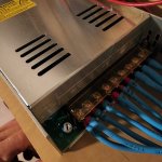
5/8" id might be a little small and why it's pulling so many amps. I wrapped mine around a 7/8" socket. I did several variations. I ended up with 9 wraps. Are you planning on water cooling? I also have 36v power supply, I attached a picture with my adjustment screw. It's white and to the left of all my wires.
Attachments
Yes, I will water cool. I haven't hooked the pump up yet. I thought I had read 5/8 was a good size, especially for 308 and 223 sized cases. I'll try to expand the coils out to a larger diameter. Is yours 1/8 tubing or different?
I just "unwrapped" two coils by hand and used the same length tubing. This expanded the ID to a ballpark of .970. It dropped the amps to about 16. I'll probably do this again, maybe just one coil at time.1/8" tubing. Honestly I never tried smaller or larger than 7/8". I just did + or - wraps. I ended up with 9.
Here's a pic of the 48v. The Phillips screw head is structural I'm pretty sure. It is tight to the right and snaps loose to the left.
Attachments
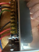
Thank you, sir. That dropped it to 38.8v and 14amp with no brass and 4 seconds.The brown plastic looking screw just to the right should be your adjustment screw.
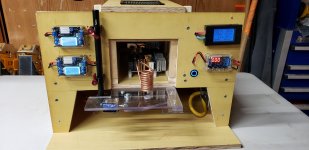
I made a video on my annealer, as I just finished a big update to it.
Big things I've learned..
1. Using table salt to wind the main coil is the way to go. Works way better than the ice methods.
2. If I built this without errors from scratch, I'd be in $850 on it. I've got more than that in it due to screw ups and parts replacements. An AMP makes a *lot* of sense.
3. You really don't need crazy power. I'm using a 1kW power supply, and this adds a lot of cost if you want to be able to handle that power effectively. 600w is fine.
But it was a fun project, and it works.
I give you, the Brass Brutalizer 1000.
Similar threads
- Replies
- 11
- Views
- 2K
- Replies
- 7
- Views
- 2K
