So when I built mine my 1st zvs board was bad right out of the gate. It burned up a couple other components in the processWondering if anyone could help me troubleshoot the power supply, relay, and ZVS side of the cicrcuit. Im using MKNZ arduino to control it and that aspect is working great.
I have a 1000W ZVS and a 48v 600w (12.5amp) power supply. With the included coil (far too big for heating brass quickly) and use of an SSR relay it works but sometimes trips the arduino overcurrent sensor. If i isolate and trigger the ssr manually it will work. However, the PS really bogs down for a moment before recovering. Pulling about 6A with just the coil. Pulls about 8A with brass. If i let it run longer than 10s it cuts out and the coils get really hot.
I wound a few other coils based on my reading this and another forum. All of them do not work at all, the PS immediately blinks out and resets. Over and over. Coils are 1/8" tubing, 28mm ID, 7-8 turns. I also wound one from 3/16" in a 5 and 7 turn config. No luck.
How do i figure out if the ZVS is bad vs. the power supply? I have watercooling ready to hook up but havent yet. Im using 12awg wire for the power connectors.
Join the Hide community
Get access to live stream, lessons, the post exchange, and chat with other snipers.
Register
Download Gravity Ballistics
Get help to accurately calculate and scope your sniper rifle using real shooting data.

Install the app
How to install the app on iOS
Follow along with the video below to see how to install our site as a web app on your home screen.
Note: This feature may not be available in some browsers.
You are using an out of date browser. It may not display this or other websites correctly.
You should upgrade or use an alternative browser.
You should upgrade or use an alternative browser.
Homemade Induction Annealer
- Thread starter TSloper
- Start date
Replacement ZVS incoming tomorrow. If still not working, will swap power supply next.
I had a board with a bad mosfet which exploded.
The chinesium is strong in these cheap parts for sure.
If you do end up replacing the power supply, I would recommend getting a larger unit...1000W ZVS <<>>1000W PS...and tighten up your coil if possible.Replacement ZVS incoming tomorrow. If still not working, will swap power supply next.
Also, I recommend a mechanical relay (unless you just can't stand the CLICK)...and a double pole where both the positive and negative are disconnected/connected simultaneously. I haven't had any issues with this configuration, and I actually appreciate the CLICK so that with the case feeder running I can do something else (nearby) and monitor the operation of the annealer by sound.
Last edited:
I have struggled getting the electrical connections figured out for the timer. I‘m truly electrically stupid. I finally got it together and was playing with the timer modes and the timer started smelling like burnt electrical. Now I don’t have voltage on the ammeter. I guess I need to order more China junk lol. I guess it’s ok because I don’t think I ordered the correct one anyway. The one I have, isn’t a ”dual” relay. So, my question is, is the “dual” used for timing the annealer AND opening/closing the trap door to release the hot brass. If not, how does the wiring/timer work to add the track door function? Thanks in advance!!
Jeff
Jeff
Update... new ZVS coil arrived today, with a desoldered coil. Ugh. Fixed it, tested with 48v 600w PS. Same problem, it bogged down the PS again. I wound a dual layer coil from wire to match inductance of the factory coil. No dice..
Hooked up 24V of auto batteries in series and managed to anneal a coil. Setup an amazon return and purchased a 48v 800W PS instead. Now I wait until saturday for another shot..
I think im going to make a dual layer coil from 1/8 tubing for my work coil to concentrate the field around the neck. Easier to match inductance that way too.
Some things to remember: (if using the Sestos B3S timer)I have struggled getting the electrical connections figured out for the timer. I‘m truly electrically stupid. I finally got it together and was playing with the timer modes and the timer started smelling like burnt electrical. Now I don’t have voltage on the ammeter.
- AC power into connectors #9 and #10 (hot and neutral)
- Low voltage (ie 12V) into connectors #4 and #7 to get switched voltage out of corresponding NO or NC pins
- The control connector pins, #2 (Start), #12 (Stop), and #11 (Gate) are for continuity connections only, no voltage...just use a momentary-on switch/button to connect them to the #1 (common) pin to enter the desired command
The dual mode timer actually has 4 timer modesThe one I have, isn’t a ”dual” relay. So, my question is, is the “dual” used for timing the annealer AND opening/closing the trap door to release the hot brass. If not, how does the wiring/timer work to add the track door function?
- the A timer is used with the #4 connector internal relay to control a large relay to switch on/off the ZVS board
- the B timer is generally set to 0.00 unless you need time between the end of annealing and dropping the case
- the C timer is used with the #7 connector internal relay to actuate the drop solenoid/mechanism. A short period of 0.50 is usually enough time for the case to drop clear
- the D timer is for the delay between dropping the case and starting the next annealing cycle (in the continuous loop mode)
Here is the PDF Manual:

New 48v, 800w 16.67a power supply (labeled LED power supply) arrived. Set it up with a rocker switch to test. PS (+) to ZVS+, rocker switch is setup on the (-) side between PS and ZVS unit
Turning it on immediately kills the PS and have to unplug and let it sit to reset it.
Im at the point of asking for recommendations for a PS. My ZVS driver works fine on battery power, cant seem to find a PS that can handle the inrush current needed.
Turning it on immediately kills the PS and have to unplug and let it sit to reset it.
Im at the point of asking for recommendations for a PS. My ZVS driver works fine on battery power, cant seem to find a PS that can handle the inrush current needed.
What coil are you using? Sounds like its the coil not the power supply. Also my understanding is it should only need to run no more than 8 seconds or so and thats depending how you have it set up. Mine has a slight delay when my cycle starts so my max time is 7.8 seconds. Technically its probably more like 5 or 6 seconds. At the end of my cycle its pulling 550 watts +/- and 14 amps +/-, and that is very brief. I just have a 36v 16.7 amp power supply. How many watts and amps are you pulling? I am no expert by any means. But if you are using the coil that it came with, its way big. Try 1/8" id tubing and wrap it around a socket thats about 7/8" diameter. Try 9 or 10 wraps, and make sure you have a small gap between each wrap. You might have to try several variations to get it right. I attached a picture of my coils I made. I actually ended up with the one with 9 wraps. I just soldered my 1/8 " tubing inside 1/4" tubing where it attached to the zvs board. Plus mine is water cooled and 1/4" fittings are easier to find. Like I said it was totally out of my wheelhouse but I figured it out for the most part with help from my brother and this thread. Hope this helps.Update... new ZVS coil arrived today, with a desoldered coil. Ugh. Fixed it, tested with 48v 600w PS. Same problem, it bogged down the PS again. I wound a dual layer coil from wire to match inductance of the factory coil. No dice..
Hooked up 24V of auto batteries in series and managed to anneal a coil. Setup an amazon return and purchased a 48v 800W PS instead. Now I wait until saturday for another shot..
I think im going to make a dual layer coil from 1/8 tubing for my work coil to concentrate the field around the neck. Easier to match inductance that way too.
Attachments
The ZVS works with a 24v battery source. I have also wound a number of coil designs and they work with the battery. None of them work with either PS that i have tried.
Edit.. maybe not. Testing a new coil and blew the ZVS while under 24V battery load. Back to square one.
Edit.. maybe not. Testing a new coil and blew the ZVS while under 24V battery load. Back to square one.
Last edited:
Interesting! Maybe its in your wiring configuration? When you wire it up to the power source. Have you tested the power source without the zvs board hooked up? Is the voltage correct? Are you hooked up to an ammeter? Not an expert just trying to help. I had to put in a ssr I kept cooking trigger modules. I had a few hiccups myself.The ZVS works with a 24v battery source. I have also wound a number of coil designs and they work with the battery. None of them work with either PS that i have tried.
Some things to remember: (if using the Sestos B3S timer)
- AC power into connectors #9 and #10 (hot and neutral)
- Low voltage (ie 12V) into connectors #4 and #7 to get switched voltage out of corresponding NO or NC pins
- The control connector pins, #2 (Start), #12 (Stop), and #11 (Gate) are for continuity connections only, no voltage...just use a momentary-on switch/button to connect them to the #1 (common) pin to enter the desired command
The dual mode timer actually has 4 timer modes
- the A timer is used with the #4 connector internal relay to control a large relay to switch on/off the ZVS board
- the B timer is generally set to 0.00 unless you need time between the end of annealing and dropping the case
- the C timer is used with the #7 connector internal relay to actuate the drop solenoid/mechanism. A short period of 0.50 is usually enough time for the case to drop clear
- the D timer is for the delay between dropping the case and starting the next annealing cycle (in the continuous loop mode)
Here is the PDF Manual:
This is awesome help above, thank you!!!
I hope this is my last dilemma. From your diagram, I have a separate 12v power supply so I do not need to reduce the 48v to 12v. But I don’t understand the type of relay you have. Can you explain that? Thank you again.
jeff
I tested both power supplies. They deliver 48V at the DC out terminals. When i connect to the ZVS i am using a simple switch to disconnect (no SSR right now). I then start the power supply up. As soon as I flip switch, it causes the PS to shut down (assuming overcurrent).
Sounds like a bad zvs board again. Try the yoosoo brand. Are you running a timer control module?I tested both power supplies. They deliver 48V at the DC out terminals. When i connect to the ZVS i am using a simple switch to disconnect (no SSR right now). I then start the power supply up. As soon as I flip switch, it causes the PS to shut down (assuming overcurrent).
Some other thoughts (just spitballing here...):
- make sure your coil wraps don't touch each other anywhere...use a piece of thin string and start at one end of the coil and slide it around all the loops until you get to the other end...it should never get caught.
- something I've heard on at least a couple occasions is to never power up the ZVS without a coil attached...not sure why
- the following is a copy of a post I made on another annealer building forum thread:
------------------------------------
The inexpensive Amazon SSR's are junk and most agree that they are not actually built to the specs advertised.
I have a 48V/1000W power supply, and I use a double pole mechanical relay so that I can use 12V to actuate the relay and switch both the positive and negative poles from the 48V power supply to the ZVS board.
This is the one I've been using, and although it shows the switching to be limited to 250V AC / 28V DC, it is 30 Amps. So far, I have had no issues with 48V and about 15-20 Amps.
--------------------------------------
Thank you for helping me brainstorm this. Can you tell me what PS you are using?
I have an arduino based controller that will trigger a SSR but right now to test Im just running power supply, ZVS with coil attached and a manual rocker switch until i figure out the heat side of the setup.
I have an arduino based controller that will trigger a SSR but right now to test Im just running power supply, ZVS with coil attached and a manual rocker switch until i figure out the heat side of the setup.
The PS I'm using now is this 48V/1500W I got off Amazon (Canadian Amazon) because they were a good price at the time I found them...Thank you for helping me brainstorm this. Can you tell me what PS you are using?
I have an arduino based controller that will trigger a SSR but right now to test Im just running power supply, ZVS with coil attached and a manual rocker switch until i figure out the heat side of the setup.
but I started with a 48V/1000W model, also off Amazon, and it worked fine (still have it for a backup if needed).
Like these:
As far as the relay is concerned, an Arduino compatible relay board should easily switch the 12 volts needed to actuate the larger relay needed to switch the ZVS board. But, again, I recommend a double pole relay to switch on/off both the positive and negative 48V power.
Last edited:
What do you mean "trips the Arduino overcurrent sensor"? If it's the one in the MGNZ code, using the current sensor they recommend? That shouldn't trigger that low, but regardless, you can edit the code and raise the current limit if you need.
Checking the SSR is a good idea. Those can be junk.
Lastly, you may need shielding. I'm fighting an inductive noise problem right now in my setup that causes my arduino to freak out and reset. Consider shielding the control board, and putting chokes on various long wires to dampen the EMF in the circuits. The noise coming out of the inductive circuit might inulduce voltage who knows where, and with all the digital signals going to servos, displays, etc stuff can get messed up. Doesn't take much either since everything is usually 5v max on the control side.
If you can use twisted, shielded pairs and run the shield to chassis ground on at least one end that will get rid of problems in the signal wires.
I prefer both ends grounded on the shield in most instances.
I prefer both ends grounded on the shield in most instances.
Last edited:
Some other thoughts (just spitballing here...):
- make sure your coil wraps don't touch each other anywhere...use a piece of thin string and start at one end of the coil and slide it around all the loops until you get to the other end...it should never get caught.
- something I've heard on at least a couple occasions is to never power up the ZVS without a coil attached...not sure why
- the following is a copy of a post I made on another annealer building forum thread:
------------------------------------
The inexpensive Amazon SSR's are junk and most agree that they are not actually built to the specs advertised.
I have a 48V/1000W power supply, and I use a double pole mechanical relay so that I can use 12V to actuate the relay and switch both the positive and negative poles from the 48V power supply to the ZVS board.
This is the one I've been using, and although it shows the switching to be limited to 250V AC / 28V DC, it is 30 Amps. So far, I have had no issues with 48V and about 15-20 Amps.
--------------------------------------
So, on your comment about why not to power up the ZVS without a work coil. Looking at the schematic and based on my limited understanding of how these circuits work, if you don't have that inductor, you don't get oscillation between the mosfets. I think this would basically end up with a constant short load through just one mosfet and probably smoke it.
I also learned that you can make sure both mosfets are working by putting LEDs on the drains to ground, and they'll light up if that mosfet is being used. http://www.kiblerelectronics.com/bob/app_notes/note11/note11.html
Last edited:
Decided to redo my induction annealing unit. I added an automatic case drop. Overall the annealer works great and has been in service since last summer.
I added another stepper and timer to run the solenoid. I have it set to run after a 6 second delay and it only runs for 0.2 seconds. All in all I am happy with the project. I posted a short video showing the case drop in action it's in the link below. If the link doesn't work I apologize. It's my first attempt posting a video on YouTube.


I added another stepper and timer to run the solenoid. I have it set to run after a 6 second delay and it only runs for 0.2 seconds. All in all I am happy with the project. I posted a short video showing the case drop in action it's in the link below. If the link doesn't work I apologize. It's my first attempt posting a video on YouTube.
I purchased the exact relay you suggested. Can you please explain the exact wiring? I can’t figure it out. I have watched many YouTube videos but none seem to show/explain the wiring perfectly. The two vertical tabs are labeled 7&8 and as I’m looking at it are on the bottom. The horizontal tabs are 1,3,5 on the left. 2,4,6 are on the right. I appreciate all of your coaching and I apologized that I am so mentally challenged. I also got the timer.This is awesome help above, thank you!!!
View attachment 7826436
I hope this is my last dilemma. From your diagram, I have a separate 12v power supply so I do not need to reduce the 48v to 12v. But I don’t understand the type of relay you have. Can you explain that? Thank you again.
jeff
Jeff
Alrighty guys. I am up and running. The Yosoo board is the right one.. my power supply is now giving 16 amps during the anneal cycle and it gets my junky test brass glowing in about 2.5 - 3 seconds with the 48V, 12.5a power supply.
At this point I am ready to get it into a case and get the water cooling setup!
At this point I am ready to get it into a case and get the water cooling setup!
Here is a pic to help explain:I purchased the exact relay you suggested. Can you please explain the exact wiring? I can’t figure it out. I have watched many YouTube videos but none seem to show/explain the wiring perfectly. The two vertical tabs are labeled 7&8 and as I’m looking at it are on the bottom. The horizontal tabs are 1,3,5 on the left. 2,4,6 are on the right. I appreciate all of your coaching and I apologized that I am so mentally challenged. I also got the timer.
Jeff
Edit: It may be unclear, but in the red box, only the connection blades are relevant. That other metal part on the left side is just a mounting bracket.
Last edited:
A couple misc questions...
For those who have setup their annealers in a project box enclosure.. can you share how you mounted the electronics? I was thinking of using tape-on standoffs for various circuit boards but wondering about power supply and especially the ZVS mounting.
Anyone add heatsinks or fans to their ZVS units? How did you mount?
Finally.. in a few builds I've seen a linear guide rail and screw system to adjust shelf height. Looking for details (pics, link) on how to set it up. I could go motorized but a simple hand turn knob would do nicely.
Many thanks @hdmunger for all the guidance. I’m sort of up and running lol.…unautomated. I have a light switch to turn the ZVS on/off and I can get a 6 CM case glowing in 4-5 seconds. Sestos timer still on a slow boat from somewhere unknown. Maybe the remaining steps will make more sense when I have the timer. But I’m still struggling conceptually with the relay and timer integration. Specifically, how do you input 48v into the relay and get 48v out to the ZVS? I hooked up the relay but don’t seem to get the correct outputs with a voltmeter.
Okay, here is a simplified schematic of the electrical part of my build:Many thanks @hdmunger for all the guidance. I’m sort of up and running lol.…unautomated. I have a light switch to turn the ZVS on/off and I can get a 6 CM case glowing in 4-5 seconds. Sestos timer still on a slow boat from somewhere unknown. Maybe the remaining steps will make more sense when I have the timer. But I’m still struggling conceptually with the relay and timer integration. Specifically, how do you input 48v into the relay and get 48v out to the ZVS? I hooked up the relay but don’t seem to get the correct outputs with a voltmeter.
First, you have to think of a relay as having 2 modes (upper right corner). The first mode is when it is unpowered, and the input signal/current is going into the common (center) contact. That contact is NOT connected to the NO (normally open) contact, but IS connected to the NC (normally closed) contact. When the relay is activated, The NO contact connects with the Common contact and the NC contact disconnects.
The normal use for the relay is to connect the Common input to the NO output when the relay activates. An alternate use is to use the NC output and the Common input to switch something OFF when the relay is activated and the normally closed contact opens.
The big relay used to switch the ZVS board on and off, in my build/schematic, has 2 internal relays running in parallel to connect/disconnect both the 48V+ and 48V- wires.
A normal relay usually has 5 contacts, V+, V-, NO, Comm, NC...where V+ and V- control the internal switch and the internal switch controls whether the Common contact is connected to NO or NC. The big relay I use has an additional set of NO, Comm, and NC contacts for a second internal switch that runs in parallel to other...both are either ON or OFF.
Power Sources:
- The 48V DC power supply and the Sestos timer both run on 110V AC
- The big relay is controlled by 12V DC from whatever source you have (separate power supply, buck converter, whatever) and is used to switch on and off the 48V DC from the power supply to the ZVS board
- The ZVS board is the only use of the 48V DC output from the power supply (generally)
Going back to the earlier discussion of the the Sestos timer, it has 4 timers that run consecutively, one after another. Timers A and C each have an internal relay that is activated while that timer is running. The A timer/relay is generally used to switch on the ZVS board for the length of time timer A is running. The C timer/relay is used to activate the drop solenoid while it is running...generally for a very short duration of about 1/2 second. Both of those instances use the NO contact to turn on the component they control, when activated.
So, to make a long story longer, here is a step-by-step progression of the normal timer cycle:
- press Start button for the timer to begin
- timer A runs, its relay closes, which closes the big relay and the 48V supply is connected to the ZVS board
- timer A ends, its relay opens, which opens the big relay and the ZVS board is powered down
- timer B runs, generally set to 0 seconds because nothing needs waiting for at this point
- timer C runs, briefly, and its relay activates the solenoid which drops the newly annealed case, then ends
- timer D runs, for however long you need before the cycle can be started again (load another case, let the ZVS/coil cool, whatever your needs are)
At this point the cycle will end or re-start, depending on the mode the timer is in (once then stop, or repeating).
I just went back and re-read this post...it meanders and repeats itself...and I'm too tired to go back and edit it again...sorry.
Edit: Okay, just went back and looked at the schematic again, and realized I didn't address the timer Start, Stop, and Gate switches (this confused me back when I first started). Firstly, there is no voltage associated with these switches, just momentary connections between the 0V (common) contact and the contacts for each command. What I mean is you just connect the 0V contact to one pole of a momentary switch and the Start contact to the other pole, and when you press the switch it connects the two and the timer receives the Start command.
Last edited:
Once again, a million thanks!! I’m sorry I’m such a knuckle head with electricity. Everytime I think I understand and start hooking up wires, it smells like burning electronics lol. The simplified schematic should get me over the hump. Thx!!
Hi, all. Finally finished the rebuild of my induction annealer!
Here is a pic of the original build
Rebuilt it into a full-tower computer case so that I would have room above the ZVS board and coolant system for the automatic case feeder.
Some things I've added since the original build:
- case feeder
- counter
- dual temperature display (coolant tank and ZVS connection to coil)
- flame sensor (can be used as primary case drop activator with the timer set to a little longer than the case needs, or as a backup to the timer in the event a case reaches flame sensor threshold before timer runs out...can also be switched off so that the timer is the only control)
- also, I replaced the 48V to 12V buck converter and used a computer power supply to provide all the 12V, 5V, and 3.3V power to run components not directly associated with the ZVS board, which also reduces the load on the 48V power supply
Here is a view with the case feeder cover closed and open (sorry its kind of dark in there...).
Tried to keep it as clean as possible for the view through the glass side of the computer case.
Not so clean looking on the other side, but I shouldn't have to look at it very often.
Here is a 'close-up' of the area around the ZVS board...hard to see anything with that cooling fan in the way.
Here is a video of me rambling while I run a 5 case demo (I think the counter double-counted one of the cases...hmm).
Thanks to all who provided direct help and to those that provided inspiration...I appreciate it.
PS - Originally I was building this in a white case and it was going to be called 'Storm Trooper', but I screwed that case up and could only get a black one, so it'll be called.......'Darth'.
And for those interested, here is a schematic of my build at this point...
Last edited:
Wow. I admire your fabricating skills!
By some miracle ive got my crude setup running in a hastily constructed plywood box... Just waiting for my drop solenoid to arrive and wire in a computer plug for AC power and its all done. I should come up with some way to raise and lower the shelf but it handles my 223 and 7mm08 just fine...

MKNZ arduino, case feed and load shelf. Some switches, an LED display, and water cooling. 48V 12.5amp PS (which supplies 16amp under anneal load somehow) and a separate 12V PS to power the arduino, fan, water pump.
By some miracle ive got my crude setup running in a hastily constructed plywood box... Just waiting for my drop solenoid to arrive and wire in a computer plug for AC power and its all done. I should come up with some way to raise and lower the shelf but it handles my 223 and 7mm08 just fine...
MKNZ arduino, case feed and load shelf. Some switches, an LED display, and water cooling. 48V 12.5amp PS (which supplies 16amp under anneal load somehow) and a separate 12V PS to power the arduino, fan, water pump.
Thanks, but I can't take any credit for the computer case, but most of the rest of the parts (mounting brackets, case feeder, front coil plate and platform) were all designed in Fusion360 to specifically fit that model case and were 3D printed and I'm pleased with how they turned out.Wow. I admire your fabricating skills!
By some miracle ive got my crude setup running in a hastily constructed plywood box... Just waiting for my drop solenoid to arrive and wire in a computer plug for AC power and its all done. I should come up with some way to raise and lower the shelf but it handles my 223 and 7mm08 just fine...View attachment 7833641
MKNZ arduino, case feed and load shelf. Some switches, an LED display, and water cooling. 48V 12.5amp PS (which supplies 16amp under anneal load somehow) and a separate 12V PS to power the arduino, fan, water pump.
One observation on your build (looks very clean and well thought out by the way) is the flame sensor looks to be much closer to the coil than it needs to be. Those sensors will detect from a good distance away, and moving it up and out of the induction field would help to keep it from getting heated up as well. Oh, and case ventilation is a must.
PS - Originally I was building this in a white case and it was going to be called 'Storm Trooper', but I screwed that case up and could only get a black one, so it'll be called.......'Darth'.
You really didn't want Stormtrooper, anyway... The effect on the accuracy of anything annealed in that thing would be ... negative... LOL
If anyone is interested in a single "parts kit", I can put one up for sale in the sale forum - this has been a hoot, but I'm moving on to an AMP!
For anyone still interested.. the mgnz makes site has a height adjustment 3d print file now on the their parts list. I am going to give it a go with mine.
I have had a notable improvement on my annealing time and consistency since rebuilding my annealing machine. The biggest thing that I did change with this build was the ability to adjust my case up or down in the coil. I have been able to fine tune the height and improve the anneal. I added the case drop also but the other components we reused.
To anyone thinking about doing the project...I say jump in and make one. My first one intimidated the hell out of me. I am a mechanical guy and do not do electrical and I managed to build mine without to much fuss. My biggest issue was me. Once I purchased the bulk of my parts I was overwhelmed with the job and thought that I was in over my head. I said to hell with it and started in on my first setup, that was all she wrote. Not as hard as I was making it out to be. I had great results, probably the second best improvements to my SD and ES overall, behind switching to a mandrel die.
Good luck.
Hi,
Thank you for your help in advance.
I've been working on MKNZ arduino based annealer currently. It has been working fine but SSR keep shorting and puts my induction coil in a "runaway train" state. Melted a case or two already.
I took advice from @hdmunger and ordered (Same one he suggested) a general purpose 2 gate relay. The output from the Control board that supplies the SSR is only around 6V (See pic). Unfortunately the general purpose relay operates at 12V. The General purpose relay is not being tripped. I did check the voltage output from the Control board when I activate the start button and the relay is only getting 6V.
I will reach out to MKNZ but is there a way to use that 6V signal to activate the 12V general purpose relay?
Please excuse my lack of electrical knowledge. I do not working in that field.
Attachments
When I made that suggestion for relays, I wasn't aware you were using 6 volts to switch your SSR...my bad.Hi,
Thank you for your help in advance.
I've been working on MKNZ arduino based annealer currently. It has been working fine but SSR keep shorting and puts my induction coil in a "runaway train" state. Melted a case or two already.
I took advice from @hdmunger and ordered (Same one he suggested) a general purpose 2 gate relay. The output from the Control board that supplies the SSR is only around 6V (See pic). Unfortunately the general purpose relay operates at 12V. The General purpose relay is not being tripped. I did check the voltage output from the Control board when I activate the start button and the relay is only getting 6V.
I will reach out to MKNZ but is there a way to use that 6V signal to activate the 12V general purpose relay?
Please excuse my lack of electrical knowledge. I do not working in that field.
I saw your posts on the other forum (which shall not be named), and if you have access to 12V power in your build, you could use that first suggestion to use the SSR you have to switch the 12V mechanical relay in a kind of daisy chain affair (6V from arduino switches SSR, which in turn passes 12V on to activate the mechanical relay, which switches the power to the ZVS...makes my head hurt). If you don't have access to 12V, then I dunno.
The other suggestion about modifying the ZVS board to shut off the mosfets...well, that has had me scratching my head since it was first suggested, and for me, personally, seems overly complicated considering the lack of explanation/demonstration for us second graders.
Edit: Doh, just looked at the pic in your post and it looks like you have 12V in the upper right corner...powering the board I assume?
Last edited:
Hi,When I made that suggestion for relays, I wasn't aware you were using 6 volts to switch your SSR...my bad.
I saw your posts on the other forum (which shall not be named), and if you have access to 12V power in your build, you could use that first suggestion to use the SSR you have to switch the 12V mechanical relay in a kind of daisy chain affair (6V from arduino switches SSR, which in turn passes 12V on to activate the mechanical relay, which switches the power to the ZVS...makes my head hurt). If you don't have access to 12V, then I dunno.
The other suggestion about modifying the ZVS board to shut off the mosfets...well, that has had me scratching my head since it was first suggested, and for me, personally, seems overly complicated considering the lack of explanation/demonstration for us second graders.
Edit: Dope, just looked at the pic in your post and it looks like you have 12V in the upper right corner...powering the board I assume?
Thank you for reaching out. I'm still lost reading the other forum. I will take your suggestion to use the SSR and the daisy chain the mechanical relay with 12V. Thank you again.
Just finished mine up today. Many Thanks to some of the hide members for helping me out with my questions through PM’s.
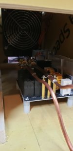
Went with a 36v 16.7a power supply that is running the ZVS board only. I currently have to 36v PS adjusted to the max at 42v. Might tinker with the voltage later. I have a separate 12v 5a power supply running all other components, timer, fans, coolant pump, etc.
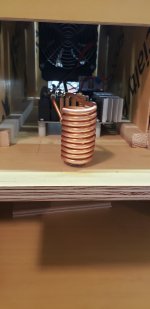
The coil is 1/8” OD copper tubing with 8 windings soldered to 1/4” tubing. Diameter is roughly 7/8” and it is 1-1/4” tall.
I made a few different coils with the same diameter but more or less windings to see what it would do. I settled on the current one because the neck on a 308 will have a faint glow at 4.5 secs. Tempilaq will be in later today and then I can fine tune it.
Currently it is peaking out at 7.3-7.4 amps and 310 watts when annealing a case. Seems low when compared to others. Checked for the normal issues but found nothing. It must be the way I have it set up....but it works.


Went with a 36v 16.7a power supply that is running the ZVS board only. I currently have to 36v PS adjusted to the max at 42v. Might tinker with the voltage later. I have a separate 12v 5a power supply running all other components, timer, fans, coolant pump, etc.
The coil is 1/8” OD copper tubing with 8 windings soldered to 1/4” tubing. Diameter is roughly 7/8” and it is 1-1/4” tall.
I made a few different coils with the same diameter but more or less windings to see what it would do. I settled on the current one because the neck on a 308 will have a faint glow at 4.5 secs. Tempilaq will be in later today and then I can fine tune it.
Currently it is peaking out at 7.3-7.4 amps and 310 watts when annealing a case. Seems low when compared to others. Checked for the normal issues but found nothing. It must be the way I have it set up....but it works.
Badass!Just finished mine up today. Many Thanks to some of the hide members for helping me out with my questions through PM’s.
Went with a 36v 16.7a power supply that is running the ZVS board only. I currently have to 36v PS adjusted to the max at 42v. Might tinker with the voltage later. I have a separate 12v 5a power supply running all other components, timer, fans, coolant pump, etc.
The coil is 1/8” OD copper tubing with 8 windings soldered to 1/4” tubing. Diameter is roughly 7/8” and it is 1-1/4” tall.
I made a few different coils with the same diameter but more or less windings to see what it would do. I settled on the current one because the neck on a 308 will have a faint glow at 4.5 secs. Tempilaq will be in later today and then I can fine tune it.
Currently it is peaking out at 7.3-7.4 amps and 310 watts when annealing a case. Seems low when compared to others. Checked for the normal issues but found nothing. It must be the way I have it set up....but it works.
View attachment 7873616
View attachment 7873617
View attachment 7873618
View attachment 7873619
View attachment 7873620View attachment 7873621
View attachment 7873622
View attachment 7873623
View attachment 7873624
Hi,
Thank you for your help in advance.
I've been working on MKNZ arduino based annealer currently. It has been working fine but SSR keep shorting and puts my induction coil in a "runaway train" state. Melted a case or two already.
I took advice from @hdmunger and ordered (Same one he suggested) a general purpose 2 gate relay. The output from the Control board that supplies the SSR is only around 6V (See pic). Unfortunately the general purpose relay operates at 12V. The General purpose relay is not being tripped. I did check the voltage output from the Control board when I activate the start button and the relay is only getting 6V.
I will reach out to MKNZ but is there a way to use that 6V signal to activate the 12V general purpose relay?
Please excuse my lack of electrical knowledge. I do not working in that field.
I originally cooked a couple SSR's in mine as well, but once I figured out that I needed to follow the wiring instructions and switch the negative lead rather than the positive lead to the zvs board, I haven't had an issue with the SSR.
Kristian
You have a great setup. What PC case is that. I see it is cooler master, but not sure what model.Just finished mine up today. Many Thanks to some of the hide members for helping me out with my questions through PM’s.
Went with a 36v 16.7a power supply that is running the ZVS board only. I currently have to 36v PS adjusted to the max at 42v. Might tinker with the voltage later. I have a separate 12v 5a power supply running all other components, timer, fans, coolant pump, etc.
The coil is 1/8” OD copper tubing with 8 windings soldered to 1/4” tubing. Diameter is roughly 7/8” and it is 1-1/4” tall.
I made a few different coils with the same diameter but more or less windings to see what it would do. I settled on the current one because the neck on a 308 will have a faint glow at 4.5 secs. Tempilaq will be in later today and then I can fine tune it.
Currently it is peaking out at 7.3-7.4 amps and 310 watts when annealing a case. Seems low when compared to others. Checked for the normal issues but found nothing. It must be the way I have it set up....but it works.
View attachment 7873616
View attachment 7873617
View attachment 7873618
View attachment 7873619
View attachment 7873620View attachment 7873621
View attachment 7873622
View attachment 7873623
View attachment 7873624
You have a great setup. What PC case is that. I see it is cooler master, but not sure what model.
Thanks Dragonetti. It’s a Cool Master - Master Box Q500L. When I first got it, I thought I wouldn’t be able to fit everything in there. But I made it work.
Similar threads
- Replies
- 11
- Views
- 2K
- Replies
- 7
- Views
- 2K
