• Watch Out for Scammers!

    We've now added a color code for all accounts. Orange accounts are new members, Blue are full members, and Green are Supporters. If you get a message about a sale from an orange account, make sure you pay attention before sending any money!

Homemade Induction Annealer

Well thank you for reviving my interest in making my own as well. I while back I made this: which was meant to be a damn close replacement to the AMP and it worked, the board just overheated. I may try the 24V power supply you're using since you seem to be running the same board as me without problems. I think the 48VDC is causing the problems w/ my board.

That looks really slick with the coil tucked inside the unit. Hopefully you're able to get it working properly. I've ordered some more solid state relays of a different brand to try in mine, hopefully they don't end up on the slow boat from china and take 3 months, I've got a bunch of brass that needs to be annealed.
Kristian
 
Well thank you for reviving my interest in making my own as well. I while back I made this: which was meant to be a damn close replacement to the AMP and it worked, the board just overheated. I may try the 24V power supply you're using since you seem to be running the same board as me without problems. I think the 48VDC is causing the problems w/ my board.

Do you have any issues with having that big chunk of metal (case holder assembly) right next to your induction coil? For instance, does it get hot too, and does it interfere with the induction field?
 
Here are the primary components...

ZVS Board ($36.62) - https://www.amazon.com/gp/product/B01C70G7Y8/ref=ppx_yo_dt_b_asin_title_o08_s00?ie=UTF8&psc=1

5-36V Timer/Relay Board ($12.99) - https://www.amazon.com/gp/product/B07V24WJ4S/ref=ppx_yo_dt_b_asin_title_o05_s00?ie=UTF8&psc=1

24V/15A Power Supply ($21.99) - https://www.amazon.com/gp/product/B0196PXMTU/ref=ppx_yo_dt_b_asin_title_o07_s00?ie=UTF8&psc=1

Momentary Switch ($8.99) - https://www.amazon.com/gp/product/B06XSBYNM7/ref=ppx_yo_dt_b_asin_title_o04_s00?ie=UTF8&psc=1

750F Tempilaq ($30.49) - https://www.amazon.com/gp/product/B00PL7SEUU/ref=ppx_yo_dt_b_asin_title_o06_s00?ie=UTF8&psc=1

Copper Wire ($17.87) - https://www.lowes.com/pd/Southwire-25-ft-8-Gauge-Soft-drawn-Copper-Bare-Wire-By-the-Roll/50372842

Cord for power supply - Lowes carries a wall plug cord that is has the L/N/GND wires exposed. Just go to where they sell extension cords and you will find it.

Feel free to ask questions. The coil winding is key. My coil is 10 turns with an ID of 15-16mm. I wouldn't go more than 20mm if you adhere to the setup above. If you aren't sure your coil dimensions/turns will work message me and I can tell you if it will work acceptably. I will need to know coil wire diameter, coil turns, and ID. The opening of the case mouth is positioned to be right about mid way in the coil.

Other timer boards can be used but make sure it supports the voltage/current needs. The timer board I used is using two N-channel FETs in parallel rather than traditional relays. It is working very well. Other ZVS boards can be used as well but you will have to take note of how much capacitance the board has when deciding the coil specs. I'm an EE btw so this project was right up my alley.

Quick tip on turning the coil with that particular wire... use a wooden dowel or similar and turn the coil as tight as possible. Once it is turned take 5-6 business cards and slide them through the coil windings. This will then give you uniform spacing between the coils. Just make sure none of the coils touch and you will be fine. At the mounting ends of the coil I just soldered the 8 AWG wire into the center of a couple pieces of 1/4" copper tubing. This allowed the coil to mount as intended with this particular ZVS board.

If you opt to mimic the wooden block approach the proper drill bit size for 223 is 13/32". You want just enough clearance that the case will drop freely but not tilt excessively. I made the base board hole under that 1/2". Everyone will have their own approaches but just make sure you dimension the case support such that the case mouth opening is about mid way in the coil.

Tim
Tsloper,

do you have a schematic of your build?
 
I finally got my new solid state relays and a heatsink. Hopefully I won't need the heatsink, because I won't be able to cram it in the computer case without a ton of work redesigning things. Turns out it can actually matter where in the circuit your load is with these things, and the new ones came with a wiring diagram. It says I had the relay wired wrong last time, and now it seems to work fine and not generate any heat at all. I'm working a night shift where I'm basically just here in case something breaks down, so there can be lots of time for projects. I tidied up my wiring and gave it a bit of a test run with some crappy brass that I don't really care about. I made my trap door adjustable height using a short Arca Swiss rail and a cheap clamp. I tried it out with some Federal 30-06 brass and IVI 7.62 brass. About 3.2 seconds for the 30-06 and 4.7 with the 7.62. They must be different compositions to be that different on time, but they draw about the same amount of current when adjusted to the same height in the coil. Turns out my current meter is a bit off, it reads about half what my Fluke clamp on meter shows. Could be just a scaling issue. Depending on where I put the case in the coil, it draws between 12 and 14 A.
IMG_20210507_234851_copy_1459x1094.jpg
IMG_20210507_234736_copy_1459x1945.jpg
IMG_20210507_223326_copy_1459x1094.jpg
 
I am finally going to dive into making my own annealer. I am currently getting different parts together in my amazon cart.

I found a 48v 600w power supply for decent price and a 1800 ZVS with built in fans. I was thinking about wiring the power supplies in parallel. I am not familiar with ZVS's or this type of supply, but I assume the ZVS won't be worked too hard so it won't be drawing much current.

Am I out to lunch with this thinking? Here are links to the products:

48v 600w Powersupply https://www.amazon.ca/gp/product/B08W3HYLQ3/ref=crt_ewc_img_dp_4?ie=UTF8&psc=1&smid=A1STPHXK2F7NH4

1800w ZVS with fans https://www.amazon.ca/gp/product/B07DVTFL14/ref=crt_ewc_title_dp_5?ie=UTF8&psc=1&smid=A3UOH6UFKYX3BS
My build uses a 48v 600w supply and it needs more current.

Edit: skimmed your post too fast.

If your supply allows parallel linking then you will be good. Set the voltages with a meter individually then connect them.
 
Last edited:
I am finally going to dive into making my own annealer. I am currently getting different parts together in my amazon cart.

I found a 48v 600w power supply for decent price and a 1800 ZVS with built in fans. I was thinking about wiring the power supplies in parallel. I am not familiar with ZVS's or this type of supply, but I assume the ZVS won't be worked too hard so it won't be drawing much current.

Am I out to lunch with this thinking? Here are links to the products:

48v 600w Powersupply https://www.amazon.ca/gp/product/B08W3HYLQ3/ref=crt_ewc_img_dp_4?ie=UTF8&psc=1&smid=A1STPHXK2F7NH4

1800w ZVS with fans https://www.amazon.ca/gp/product/B07DVTFL14/ref=crt_ewc_title_dp_5?ie=UTF8&psc=1&smid=A3UOH6UFKYX3BS
Are you thinking about using two of the 600w supplies in parallel? I've never done that with switching power supplies, but I would think they would have to be very closely matched to make it work. It would be not a lot more money and probably much less headaches to go with a single larger supply. If you're wanting to use a single 600w supply, it can work, but as mentioned you would have to be pretty careful about current draw.
Kristian

The meanwell brand I use specifies in the manual that it is possible to do so. The one he has linked, may need to read whatever documentation is provided.
 
Thanks for the information gents. I will look harder for a 1kW one. That ZVS looks good to go?
 
Thanks for the information gents. I will look harder for a 1kW one. That ZVS looks good to go?


I think most including myself have gone with the 1kw version. It is the same principle of course, but I have no idea what kind of frequency it will resonate at. I would venture to guess that it will be just fine if you test a couple coils and have a strong power source.

The original poster could help with proper coil dimensions, but he hasn't been on here in some time.
 
Just put in my order. Ended up going with a 48v 1kw power supply and a 1kw ZVS. I also got a pair of fans, assorted switches, solenoid, a nice timer, step-down converter, and water cooling system. All in it was just over 300 Canuck-Bucks.

Hopefully it all works together fairly well. Will take a month for the slow boat from china to arrive with the components.
 
  • Like
Reactions: Bradv86
Just put in my order. Ended up going with a 48v 1kw power supply and a 1kw ZVS. I also got a pair of fans, assorted switches, solenoid, a nice timer, step-down converter, and water cooling system. All in it was just over 300 Canuck-Bucks.

Hopefully it all works together fairly well. Will take a month for the slow boat from china to arrive with the components.
If you get the coil close to right it should be fine, it seems like many others have used similar setups.
Kristian
 
I am finally going to dive into making my own annealer. I am currently getting different parts together in my amazon cart.

I found a 48v 600w power supply for decent price and a 1800 ZVS with built in fans. I was thinking about wiring the power supplies in parallel. I am not familiar with ZVS's or this type of supply, but I assume the ZVS won't be worked too hard so it won't be drawing much current.

Am I out to lunch with this thinking? Here are links to the products:

48v 600w Powersupply https://www.amazon.ca/gp/product/B08W3HYLQ3/ref=crt_ewc_img_dp_4?ie=UTF8&psc=1&smid=A1STPHXK2F7NH4

1800w ZVS with fans https://www.amazon.ca/gp/product/B07DVTFL14/ref=crt_ewc_title_dp_5?ie=UTF8&psc=1&smid=A3UOH6UFKYX3BS
I would recommend the following power supply, I have build my Annealer using the 1800W ZVS board, it draws between 18A to 22A, it anneals 30.06 DA surplus brass in 3.3 secs, Lapua 308 in 3.1 secs.

 
I finally got my new solid state relays and a heatsink. Hopefully I won't need the heatsink, because I won't be able to cram it in the computer case without a ton of work redesigning things. Turns out it can actually matter where in the circuit your load is with these things, and the new ones came with a wiring diagram. It says I had the relay wired wrong last time, and now it seems to work fine and not generate any heat at all. I'm working a night shift where I'm basically just here in case something breaks down, so there can be lots of time for projects. I tidied up my wiring and gave it a bit of a test run with some crappy brass that I don't really care about. I made my trap door adjustable height using a short Arca Swiss rail and a cheap clamp. I tried it out with some Federal 30-06 brass and IVI 7.62 brass. About 3.2 seconds for the 30-06 and 4.7 with the 7.62. They must be different compositions to be that different on time, but they draw about the same amount of current when adjusted to the same height in the coil. Turns out my current meter is a bit off, it reads about half what my Fluke clamp on meter shows. Could be just a scaling issue. Depending on where I put the case in the coil, it draws between 12 and 14 A.
View attachment 7620676View attachment 7620677View attachment 7620678
What case are you using?
 
I got the new RevC induction board from Mark at MGNZ last week and got it up and running today using a Makerbase closed loop stepper to run the case feeder. All automatic now, I reckon it's pretty posh!

 
I had a few different feeder wheels for different sized cases, I saw a brilliant idea on youtube using magnets to locate a rotating feeder drum. I made one up with 223, 308 and magnum feed slots, it can switch between the 3 without any tools which makes it pretty quick to swap from one size to the next. Excuse the very rough video and 3d printing job, I just wanted to see if it would work. Time to make a nice job of it now.


1622684373677.png

1622684407034.png
 
Well I am having issues. First off, this is my first attempt at something like this and to be honest I was a little confused and intimidated. I managed to get it running but am having issues with my coil size and power draw. I'm running a 36v 750w power supply and have only managed to draw about 9amps at 340w. I've hit about 500F with my current coil size. I'm going to run a smaller diameter tubing to achieve a smaller coil diameter. Again this is my first go at it so I'm sure there is something I can do better. I've got a water pump, heat exchanger with fan that I will connect once I figure my coil size out.
20210605_174051.jpg
 
Well I am having issues. First off, this is my first attempt at something like this and to be honest I was a little confused and intimidated. I managed to get it running but am having issues with my coil size and power draw. I'm running a 36v 750w power supply and have only managed to draw about 9amps at 340w. I've hit about 500F with my current coil size. I'm going to run a smaller diameter tubing to achieve a smaller coil diameter. Again this is my first go at it so I'm sure there is something I can do better. I've got a water pump, heat exchanger with fan that I will connect once I figure my coil size out.
View attachment 7641124

Search back in this thread. You have the same ZVS board as me and if you copy my small coil from 1/8" tubing I think it will run nicely. The larger coil I made from 3/16 would probably also work well if you are able to adjust the voltage higher.

Just heated some Starline .223 today and it is still working well.
 

Attachments

  • IMG_20210605_133618134.jpg
    IMG_20210605_133618134.jpg
    385.8 KB · Views: 179
Well I am having issues. First off, this is my first attempt at something like this and to be honest I was a little confused and intimidated. I managed to get it running but am having issues with my coil size and power draw. I'm running a 36v 750w power supply and have only managed to draw about 9amps at 340w. I've hit about 500F with my current coil size. I'm going to run a smaller diameter tubing to achieve a smaller coil diameter. Again this is my first go at it so I'm sure there is something I can do better. I've got a water pump, heat exchanger with fan that I will connect once I figure my coil size out.
View attachment 7641124
Grab some 1/8" or 3mm tube, wrap it 7 1/2 turns around something 1 1/8" diameter and see what that does. It seems to be the standard for these ZVF annealer boards. Any reason you went with a 36 rather than 48V power supply? I'm just relying on the "wisdom of the crowd" but that would be my first suggestion. (y)
 
Grab some 1/8" or 3mm tube, wrap it 7 1/2 turns around something 1 1/8" diameter and see what that does. It seems to be the standard for these ZVF annealer boards. Any reason you went with a 36 rather than 48V power supply? I'm just relying on the "wisdom of the crowd" but that would be my first suggestion. (y)
I am not the brightest when it comes to electrical. I guess I could have asked for some help but its been a while since I read through this thread. I've actually read through it a couple times but again it's been a while.
I could only find a 36v timer and so I matched it up with a power source. Figured I could get it going.
I don't really anneal a whole lot. Maybe around 300-400 cases a month tops. I didn't want to put to much into something I wasn't sure I was going to be able utilize or get working. I do like the consistency of induction annealing so here I am. I am hoping I can get it going. It will definitely save me some money over buying an amp.
 
Update: 1/8" tube with 7.5 wraps at 1" ID gets my 300WM brass white hot in about 10 seconds. I have to get a few fittings to plumb in the coil and pump and that part will be done. The pump will be set next to the fan and plumbed in. It will run through the heat exchanger on the rear fan. Next thing will be messing with case height and time, I might try a tighter coil to. All in all a pretty cool project.
I have definitely learned a lot from this. Thanks for the input.
20210606_211614.jpg
 
  • Like
Reactions: NoDopes and Gtar
Ive hooked up my water pump and can now run one after another without the coil getting hot.. Got it down to 7 seconds for my Hornady 300PRC and 300WM brass. I might bump up the time 1 second or less. I also need to find the sweet spot for my 6.5cm brass and make a trap door to drop the cases out of the bottom.
Using 750 F green , 900 F white and 1000 F rust tempilaq.
20210607_103817.jpg
20210607_104142.jpg
20210607_104137.jpg
20210607_104133.jpg
 
Ive hooked up my water pump and can now run one after another without the coil getting hot.. Got it down to 7 seconds for my Hornady 300PRC and 300WM brass. I might bump up the time 1 second or less. I also need to find the sweet spot for my 6.5cm brass and make a trap door to drop the cases out of the bottom.
Using 750 F green , 900 F white and 1000 F rust tempilaq.
View attachment 7642105View attachment 7642106View attachment 7642107View attachment 7642108
Nice work. Hornady brass tends to heat far faster than Lapua or Norma. You'll probably have similar findings.

Gotta love the way it looks when it's working IMG_20210105_221527458.jpg 😀
 
  • Like
Reactions: JBarton
Update: 1/8" tube with 7.5 wraps at 1" ID gets my 300WM brass white hot in about 10 seconds. I have to get a few fittings to plumb in the coil and pump and that part will be done. The pump will be set next to the fan and plumbed in. It will run through the heat exchanger on the rear fan. Next thing will be messing with case height and time, I might try a tighter coil to. All in all a pretty cool project.
I have definitely learned a lot from this. Thanks for the input.
View attachment 7641915
What is the resolution on your timer? I can only zoom in so far and can't tell if there is a decimal point showing. You should have at least 1/10 of a second control of the time...
 
What is the resolution on your timer? I can only zoom in so far and can't tell if there is a decimal point showing. You should have at least 1/10 of a second control of the time...
I haven't been able to get it down to the 1/10 of a second. Of course it didn't come with instructions....I am tinkering with it and should be able to get it figured out. I have a different one on order but it's a little over a month out. The one I'm currently running is not my first choice but figured it would get me going.
 
What is the resolution on your timer? I can only zoom in so far and can't tell if there is a decimal point showing. You should have at least 1/10 of a second control of the time...
I figured out how to adjust the time in 1/10th of a second increments. Thanks for asking, otherwise I'm not sure I would have dug into it.

Thanks
 
I figured out how to adjust the time in 1/10th of a second increments. Thanks for asking, otherwise I'm not sure I would have dug into it.

Thanks
Your welcome...glad to help from the peanut gallery...
 
Quick update. I had to replace the water pump and added a separate voltage regulator for the pump so I can adjust the fans and pump speeds separately. I also reduced my coil ID to 0.750" which gave me a total of 9.5 wraps. This reduced my annealing time around 40% while pulling approximately 400 watts at 14.5-14.9 amps. I'm now annealing my 300WM and 300PRC brass in 4.9 seconds and my 6.5cm brass I 6.2 seconds. I've ran multiple cases through at a fast pace..as fast as I could feed them with no heat or other issues. I am calling this a success.
I am sure I will make upgrades and improvements in the future like a bigger power supply. I would also like to set it up in an old computer tower to clean it up and reduce the overall footprint.
20210612_085223.jpg
 
  • Like
  • Love
Reactions: NoDopes and Gtar
I am sure I will make upgrades and improvements in the future like a bigger power supply. I would also like to set it up in an old computer tower to clean it up and reduce the overall footprint.
I am in the process of rebuilding my annealer into a full size tower computer case. I chose the full tower option so that I could use the 3+ CD drive bay space for an integral case feeder (as opposed to mounting it to the top/outside of the computer case). Also, a complete redesign of my case holder assembly and the coil mounting method to switch from adjusting the height of the coil (in my old design) to an adjustable height case holder.
The process is slow and ongoing due to a plethora of other projects on my plate.
 
  • Like
Reactions: JBarton
Mine is spread out on a 12"x24" piece of plywood. I don't think I could fit everything into the enclosure you found on Amazon.
Im working on getting an old computer tower.
View attachment 7646941


Yes, I think it was too small when I purchase it. I am gong to work on a computer case, since it is the cheapest solution.

I still need to purchase a few components; I have not had the time to dedicate to this. I need to find a solenoid.

Drag
 
  • Like
Reactions: JBarton
Can someone school me on how the amount of turns in a coil effect current?

I am using 1/8 copper tube, power supply dialed down to 40 vdc. I am using a mechanical relay to switch my ZVS. I had a coil with 7 turns and approximately 15/16 ID running well. It had 1/4" clearance to the case. It would get a case glowing in 5 seconds.

I had read that the closer the coil is to the case the more efficiently it heats. So I bent up a second coil with 7 turns and a tighter ID giving 1/8" clearance to the case. It is certainly more efficient, will get a case glowing in 2.5 seconds. My issue is, it is arcing at the contacts on my relay really bad during operation with the tighter coil. I suspect I am pulling too much current over the contact. I am not tripping any breakers or the powersupply. But I am on the short track to having a fire with this one.

Does current go up with more or less turns? Does current go up with a tighter ID? I suspect I already have my answer to the second question.

I would appreciate anyone who could spell this out to me in crayon.
The more/less turns is going to change the frequency that the ZVS switches at.

The tighter diameter (closer to the brass) is the main factor in what is driving the current up.
 
  • Like
Reactions: Snuby642
The more/less turns is going to change the frequency that the ZVS switches at.

The tighter diameter (closer to the brass) is the main factor in what is driving the current up.

Thank you! Will the current change with the frequency? Does frequency go up or down with the amount of turns?
 
I will see if my electronics expert will offer an answer.

He actually likes doing the math.
 
@OldRussian

So I asked my friend math and electronics teacher and this was his response.

"
Some thoughts,


If it is DC, the length of the tube, diameter, and wall thickness determine the resistance. Just measure the resistance, if you can, with an ohm meter and determine how much resistance there is in the old one vs the new one. Assuming your supply and load have not changed, then this is your resistance for DC current.


Now, you are switching the current. How often does it switch? Is this based on temperature and/or time? Is it constantly switching back and forth?


When you switch current on to an inductor, i.e., your coil, it created a counter EMF. I creates another one when you switch it off. If you inductance is larger than the last one, it would probably create a bigger counter EMF than the other one. The contacts in the relay are going to be rated for voltage and current. If you exceed the capability of the relay contacts, based on the spacing between the contacts, you might have arcing.


You can also measure the on voltage and current for the two coils to determine the difference in resistance: E/I = R


An LRC meter can allow you to measure the inductance and possibly the micro-ohms.


Good luck."

I personally think 5 seconds seems fine if it doesn't toast anything.
 
  • Like
Reactions: OldRussian
Does frequency go up or down with the amount of turns?

The inductance of a coil increases as you add more turns. Increasing the inductance lowers the resonant frequency.

A quick calculations suggest that if you use 8 turns instead of 7 on your new smaller diameter coil, this will increase the coils inductance to somewhere close to your original coil, which should bring current much closer to where it was before.

There are lots of online resources that will help you calculate inductance if you don't have a meter (e.g. Coil calculator, solenoid calculator)
I don't know of anything that can accurately predict currents for these ZVS circuit boards - maybe someone else knows ?

As snuby says, 5 seconds is a pretty good setup as it is !
 
12 rpm / 720 per hour.
If running a production shop I could see the urgency.

At some point I would think the brass could be damaged?

I have 10 or 11 thousand pieces of brass that are first and second fired, mostly 223 and a mix of others we shoot.

Getting close to using up all the first fired in several calibers so very intrested in this annealer.

I threw my back out of wack last week moving some of it around. I guess old guys should use 3 gallon buckets instead of 5 gallon.
 
Been lurking here for awhile and thanks to this thread I got my MGNZ annealer board last week and everything packaged into a mid-tower ATX case. Only issue so far is that the temp limit for the induction capacitors doesn't kick in, even though the temp reads over 60C.

I've uploaded the 3D printer files, linear rail code, and front panel cut .svg to Thingiverse here:
Induction Annealer Thing: 4930540
Still need to add some different case shelf diameters and a non-linear rail mounting option.

The computer case houses everything listed on the MGNZ parts list including a mounting spot at the top for the auto-feeder. I added a 2nd Arduino to control a small linear rail stepper for height adjustment for the case shelf.

IMG_1018.jpg
IMG_1008.jpg
IMG_1011.jpg
 
Been lurking here for awhile and thanks to this thread I got my MGNZ annealer board last week and everything packaged into a mid-tower ATX case. Only issue so far is that the temp limit for the induction capacitors doesn't kick in, even though the temp reads over 60C.

I've uploaded the 3D printer files, linear rail code, and front panel cut .svg to Thingiverse here:
Induction Annealer Thing: 4930540
Still need to add some different case shelf diameters and a non-linear rail mounting option.

The computer case houses everything listed on the MGNZ parts list including a mounting spot at the top for the auto-feeder. I added a 2nd Arduino to control a small linear rail stepper for height adjustment for the case shelf.

View attachment 7683838View attachment 7683839View attachment 7683840
Nice job! have you had any issues with the shaft on the dropper servo getting hot from being close to the induction field? I had a pivot pin on the trapdoor setup on mine in a similar location and it eventually heated up enough after a few hundred cases to bind up on the plastic. I changed it for a delrin shaft and that solved the issue. I do like the servo idea though and really like your mounting solution, I've filed that away to maybe use later on (y)
 
  • Like
Reactions: RickJ19Zeta7
Nice job! have you had any issues with the shaft on the dropper servo getting hot from being close to the induction field? I had a pivot pin on the trapdoor setup on mine in a similar location and it eventually heated up enough after a few hundred cases to bind up on the plastic. I changed it for a delrin shaft and that solved the issue. I do like the servo idea though and really like your mounting solution, I've filed that away to maybe use later on (y)
I haven't had an issue.... yet. I'm a bit concerned how close some of my screw locations are, as well as that servo shaft. It was ok after 75 or so cases in a stress test. But I need to run a longer session to see if I should space those further out from the coil.

I should probably spend some time and figure out snap fits for the shell holder and drop chute, rather than the stainless M4s button heads. Once I make some updates this weekend, Ill add the .step or .prt files to Thingiverse.
 
Here are the primary components...

ZVS Board ($36.62) - https://www.amazon.com/gp/product/B01C70G7Y8/ref=ppx_yo_dt_b_asin_title_o08_s00?ie=UTF8&psc=1

5-36V Timer/Relay Board ($12.99) - https://www.amazon.com/gp/product/B07V24WJ4S/ref=ppx_yo_dt_b_asin_title_o05_s00?ie=UTF8&psc=1

24V/15A Power Supply ($21.99) - https://www.amazon.com/gp/product/B0196PXMTU/ref=ppx_yo_dt_b_asin_title_o07_s00?ie=UTF8&psc=1

Momentary Switch ($8.99) - https://www.amazon.com/gp/product/B06XSBYNM7/ref=ppx_yo_dt_b_asin_title_o04_s00?ie=UTF8&psc=1

750F Tempilaq ($30.49) - https://www.amazon.com/gp/product/B00PL7SEUU/ref=ppx_yo_dt_b_asin_title_o06_s00?ie=UTF8&psc=1

Copper Wire ($17.87) - https://www.lowes.com/pd/Southwire-25-ft-8-Gauge-Soft-drawn-Copper-Bare-Wire-By-the-Roll/50372842

Cord for power supply - Lowes carries a wall plug cord that is has the L/N/GND wires exposed. Just go to where they sell extension cords and you will find it.

Feel free to ask questions. The coil winding is key. My coil is 10 turns with an ID of 15-16mm. I wouldn't go more than 20mm if you adhere to the setup above. If you aren't sure your coil dimensions/turns will work message me and I can tell you if it will work acceptably. I will need to know coil wire diameter, coil turns, and ID. The opening of the case mouth is positioned to be right about mid way in the coil.

Other timer boards can be used but make sure it supports the voltage/current needs. The timer board I used is using two N-channel FETs in parallel rather than traditional relays. It is working very well. Other ZVS boards can be used as well but you will have to take note of how much capacitance the board has when deciding the coil specs. I'm an EE btw so this project was right up my alley.

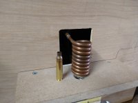
Quick tip on turning the coil with that particular wire... use a wooden dowel or similar and turn the coil as tight as possible. Once it is turned take 5-6 business cards and slide them through the coil windings. This will then give you uniform spacing between the coils. Just make sure none of the coils touch and you will be fine. At the mounting ends of the coil I just soldered the 8 AWG wire into the center of a couple pieces of 1/4" copper tubing. This allowed the coil to mount as intended with this particular ZVS board.

If you opt to mimic the wooden block approach the proper drill bit size for 223 is 13/32". You want just enough clearance that the case will drop freely but not tilt excessively. I made the base board hole under that 1/2". Everyone will have their own approaches but just make sure you dimension the case support such that the case mouth opening is about mid way in the coil.

Tim
Have you had any issues with the N FETs going out from like static from being touched I know they’re notoriously fragile. I just ordered all the parts off Amazon and it came up to $129. I refuse to pay $1395 for an “inductor”
 
  • Like
Reactions: Snuby642
I’ve only managed to get about halfway through the thread and it may be later down below where I stopped reading but has anybody thought about setting the case in water therefore negating the heat traveling down the brass with the coils that aren’t exactly correctly wound? Yes I know I’m late to the party this thread but started two years ago but nonetheless I am and electronics geek, ham radio operator, gun nut this is the best of two hobbies combined if you could only do it on the back of a Harley Davidson it would be the best of all three worlds.
 
In Liew of having a proper esd work station to work on electronics.

Take shoes and socks off.
Lay all parts on bench in thier packaging before opening.
Lay your forearms on bench and open parts.
Maintain a bare contact with bench and floor as you work.

If component has its leads stuck in foam make sure to set it on bench and touch foam before removing it.

That will keep most items safe because the next step is esd mat, wristband all grounded properly.

A grounded powder dispenser is a good idea but you can drain the static by simply touching everything while barefoot.
 
I’ve only managed to get about halfway through the thread and it may be later down below where I stopped reading but has anybody thought about setting the case in water therefore negating the heat traveling down the brass with the coils that aren’t exactly correctly wound? Yes I know I’m late to the party this thread but started two years ago but nonetheless I am and electronics geek, ham radio operator, gun nut this is the best of two hobbies combined if you could only do it on the back of a Harley Davidson it would be the best of all three worlds.

As long as the case is heated rapidly at the mouth you won't need to worry about it. The heat dissipates very quickly, especially as the case thickness increases slightly going towards the web.

If you needed water, AMP would have it sitting in water.
 
  • Like
Reactions: spife7980
that sounds amazing being able to make your own electric chair I mean annealing machine
 
  • Haha
Reactions: spife7980
I’ve only managed to get about halfway through the thread and it may be later down below where I stopped reading but has anybody thought about setting the case in water therefore negating the heat traveling down the brass with the coils that aren’t exactly correctly wound? Yes I know I’m late to the party this thread but started two years ago but nonetheless I am and electronics geek, ham radio operator, gun nut this is the best of two hobbies combined if you could only do it on the back of a Harley Davidson it would be the best of all three worlds.

Not necessary the case neck melts way before the base has reached a temperature high enough to anneal it.

On my homemade annealer the trap door that drops the case is plastic and I have melted case necks
without the base melting or sticking to the plastic.
 
  • Like
Reactions: NoDopes