Here are the primary components...
ZVS Board ($36.62) -
https://www.amazon.com/gp/product/B01C70G7Y8/ref=ppx_yo_dt_b_asin_title_o08_s00?ie=UTF8&psc=1
5-36V Timer/Relay Board ($12.99) -
https://www.amazon.com/gp/product/B07V24WJ4S/ref=ppx_yo_dt_b_asin_title_o05_s00?ie=UTF8&psc=1
24V/15A Power Supply ($21.99) -
https://www.amazon.com/gp/product/B0196PXMTU/ref=ppx_yo_dt_b_asin_title_o07_s00?ie=UTF8&psc=1
Momentary Switch ($8.99) -
https://www.amazon.com/gp/product/B06XSBYNM7/ref=ppx_yo_dt_b_asin_title_o04_s00?ie=UTF8&psc=1
750F Tempilaq ($30.49) -
https://www.amazon.com/gp/product/B00PL7SEUU/ref=ppx_yo_dt_b_asin_title_o06_s00?ie=UTF8&psc=1
Copper Wire ($17.87) -
https://www.lowes.com/pd/Southwire-25-ft-8-Gauge-Soft-drawn-Copper-Bare-Wire-By-the-Roll/50372842
Cord for power supply - Lowes carries a wall plug cord that is has the L/N/GND wires exposed. Just go to where they sell extension cords and you will find it.
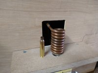
Feel free to ask questions. The coil winding is key. My coil is 10 turns with an ID of 15-16mm. I wouldn't go more than 20mm if you adhere to the setup above. If you aren't sure your coil dimensions/turns will work message me and I can tell you if it will work acceptably. I will need to know coil wire diameter, coil turns, and ID. The opening of the case mouth is positioned to be right about mid way in the coil.
Other timer boards can be used but make sure it supports the voltage/current needs. The timer board I used is using two N-channel FETs in parallel rather than traditional relays. It is working very well. Other ZVS boards can be used as well but you will have to take note of how much capacitance the board has when deciding the coil specs. I'm an EE btw so this project was right up my alley.
Quick tip on turning the coil with that particular wire... use a wooden dowel or similar and turn the coil as tight as possible. Once it is turned take 5-6 business cards and slide them through the coil windings. This will then give you uniform spacing between the coils. Just make sure none of the coils touch and you will be fine. At the mounting ends of the coil I just soldered the 8 AWG wire into the center of a couple pieces of 1/4" copper tubing. This allowed the coil to mount as intended with this particular ZVS board.
If you opt to mimic the wooden block approach the proper drill bit size for 223 is 13/32". You want just enough clearance that the case will drop freely but not tilt excessively. I made the base board hole under that 1/2". Everyone will have their own approaches but just make sure you dimension the case support such that the case mouth opening is about mid way in the coil.
Tim