Oh snap, I might have a few questions. This is up my ally to make things easier. I see that you have a custom board and uno, do you need both?Hi, That is my website and NZHS forum post. Happy to answer any questions.
Mark
Join the Hide community
Get access to live stream, lessons, the post exchange, and chat with other snipers.
Register
Download Gravity Ballistics
Get help to accurately calculate and scope your sniper rifle using real shooting data.

Install the app
How to install the app on iOS
Follow along with the video below to see how to install our site as a web app on your home screen.
Note: This feature may not be available in some browsers.
You are using an out of date browser. It may not display this or other websites correctly.
You should upgrade or use an alternative browser.
You should upgrade or use an alternative browser.
Homemade Induction Annealer
- Thread starter TSloper
- Start date
The Uno is the Arduino processor board and that plugs into the MGNZ annealer baseboard (Shield). You need both, but can use any Uno - with the open source software I have posted on github.Oh snap, I might have a few questions. This is up my ally to make things easier. I see that you have a custom board and uno, do you need both?
Hi, That is my website and NZHS forum post. Happy to answer any questions.
Mark
I know ;-) I ordered the board yesterday with you (I'm the guy from The Netherlands).
Still wondering if I did ok with ordering the 24v ZVS & 24v/1000w powersupply if I want to anneal 6.5creed, .308win & 300 norma (which is quite large) or if I should change that to 36 or 42 volt setups. (I can still cancel the order of the power supply due to delay in delivery)
ps I see that the ZVS board I ordered can also handle 36v and there are also strong 36v power supplies available . Would I potentially benefit from switching to that?
Last edited:
I know ;-) I ordered the board yesterday with you (the guy from The Netherlands).
Still wondering if I did ok with ordering the 24v ZVS & 24v/1000w powersupply if I want to anneal 6.5creed, .308win & 300 norma (which is quite large) or if I should change that to 36 or 42 volt setups. (I can still cancel the order of the power supply due to delay in delivery)
ps I see that the ZVS board I ordered can also handle 36v and there are also strong 36v power supplies available . Would I potentially benefit from switching to that?
Ah, it's you! haha.
My personal experience has been that you will struggle with the 24V supply. It will eventually anneal the case, but the time taken to hit the temperature will be quite long. The longer the case takes to anneal, the more heat will conduct down towards the case head - which isn't a good thing. 36V will be better, you will just need to do some experimentation (the 36V PSU link you have is higher power than you will be able to pull with the ZVS - 500 or 600W is enough). The tried and true option is to use the 1000W ZVS board and a 48V/600W PSU and start testing with the PSU reduced to 42V and increase it as needed. I anneal 300WM brass in <4.0s. The supply is 42V @ 9.8A during the anneal - so ~400W of input power.
Ok, clear. But will it not destroy a 6.5 creedmoor in no time? I also want to avoid that for smaller brass the time is super short & critical to manage. <4s for 300WM is already quite fast. no time for mistakes there!
Last edited:
It's actually a function of the amount of brass in the work coil and the resulting electrical loading on the ZVS. The smallest brass I anneal is .223 and that takes 2.8s. for reference .308 takes 4.9s. I don't think you will have any issues with 6.5 Creedmoor.Ok, clear. But will it not destroy a 6.5 creedmoor in no time? I also want to avoid that for smaller brass the time is super short & critical to manage. <4s for 300WM is already quite fast. no time for mistakes there!
I'm printing it now! Do you remember how you printed it? Any specific settings and the orientation of the work (I can't get in in a position that it does not require supports so maybe there is one where the supports are the least of the problem.Sure thing. I've attached a zip file containing the shelf and trap door pictured below. I cant take credit, the original author was "SGK" on Accurate Shooter.
It takes a little finagling to get it situated just right but I've had zero problems.
View attachment 7471913
Thans.
p.s. I'm now building this annealer but should go well together with this shelf design.
ps2 Noticed that the hole in the shelf is 15mm which just fits my Norma Magnum which is great!
@tyfoon Was printed with the top down and yep it had to have supports. It was actually on my brother's printer as mine isn't setup for PETG, sorry I don't know other details off hand but can ask if needed.
I've only done 6 GT and 308 cases so far which fit the larger shell holder perfect.
I've only done 6 GT and 308 cases so far which fit the larger shell holder perfect.
@tyfoon Was printed with the top down and yep it had to have supports. It was actually on my brother's printer as mine isn't setup for PETG, sorry I don't know other details off hand but can ask if needed.
I've only done 6 GT and 308 cases so far which fit the larger shell holder perfect.
Also trying to print it in ABS now. Should be even more heat resistant.
I have mounted the selenoid (seems to the same as in your picture) but the pull is very weak. Especially at the beginning of the throw. Just very little resistance will hold it back. Is this also your experience? Maybe I just got a bad one...
There certainly is not much force. The trap door/paddle on mine can basically swing freely, like with gravity if you move it around(without solenoid attached). I used little bitty screws to assemble and connect things with a washer or two for contact points.
There certainly is not much force. The trap door/paddle on mine can basically swing freely, like with gravity if you move it around(without solenoid attached). I used little bitty screws to assemble and connect things with a washer or two for contact points.
But never any issues of it not opening? When I put a 308 case on it (so on the 'paddle via the hole) it already has some issues but with a 300norma case on it, it does not even move...
I just order the board from MGNZ. I like the ability to control all the processes with a Micro Controller. I am trying to find a larger screen for the display. I am thinking of this one:
I have to look at the source code to see what to modify for the larger display.
I have to look at the source code to see what to modify for the larger display.
I just order the board from MGNZ. I like the ability to control all the processes with a Micro Controller. I am trying to find a larger screen for the display. I am thinking of this one:
I have to look at the source code to see what to modify for the larger display.
Would be nice a bigger display! I just got mine in and it's much smaller then I anticipated...
Would be nice a bigger display! I just got mine in and it's much smaller then I anticipated...
Yeah all the none color I2C oled displays are sub 1 inch. That one I posted is 1.3 inches, but pixel density is larger 128x64 vs 128x32 on the original website.
Nope. 308 is the biggest I've run but zero issues.But never any issues of it not opening? When I put a 308 case on it (so on the 'paddle via the hole) it already has some issues but with a 300norma case on it, it does not even move...
Nope. 308 is the biggest I've run but zero issues.
Has to be my solenoid then.
It's actually a function of the amount of brass in the work coil and the resulting electrical loading on the ZVS. The smallest brass I anneal is .223 and that takes 2.8s. for reference .308 takes 4.9s. I don't think you will have any issues with 6.5 Creedmoor.
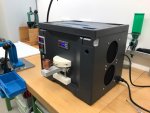
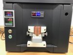
So my build is done except for your board (still in transit I guess). Used all from your build list however using a 1200w power supply instead of the 600w. Also coil is identical. Also turned the supply down to approx 43v .However for a 308 I need approx 6.1 second (I see a very very faint glow in pitch dark and Tempilaq black but green under the shoulder). Tried several types of brass (6.1s is for Lapua). Unfortunately I don't have a current meter yet.
Do you have an idea why it takes longer with me vs your 4.9 seconds?
p.s. still need to make all nice in a box etc
Last edited:

Looking good there! could be a few reasons - I think you are taking the case anneal a bit further than I do, I stop before seeing any faint glowing when I dial in my timing. Also the brass alloy and case neck thickness seem to really effect the anneal time - my .308 time was for RP brass. I don't have all my timing numbers on hand but for 300WM - Norma brass takes a lot longer than hornady did.So my build is done except for your board (still in transit I guess). Used all from your build list however using a 1200w power supply instead of the 600w. Also coil is identical. Also turned the supply down to approx 43v .However for a 308 I need approx 6.1 second (I see a very very faint glow in pitch dark and Tempilaq black but green under the shoulder). Tried several types of brass (6.1s is for Lapua). Unfortunately I don't have a current meter yet.
Do you have an idea why it takes longer with me vs your 4.9 seconds?
p.s. still need to make all nice in a box etc
View attachment 7479315
The other thing in the setup that could affect it is the wire gauge going to the ZVS board from the 48V PSU, solid state relay etc. - but your picture looks fine.
Last edited:
Looking good there! could be a few reasons - I think you are taking the case anneal a bit further than I do, I stop before seeing any faint glowing when I dial in my timing. Also the brass alloy and case neck thickness seem to really effect the anneal time - my .308 time was for RP brass. I don't have all my timing numbers on hand but for 300WM - Norma brass takes a lot longer than hornady did.
The other thing in the setup that could affect it is the wire gauge going to the ZVS board from the 48V PSU, solid state relay etc. - but your picture looks fine.
The wire is 12gauge (30A) so should be fine and the relay is identical to your's from the list.
Overall all works fine and also the 6.1s seem to be ok (heat not going down too much)
Where do you place the brass in the coil (height)?
Last edited:
Where do you place the brass in the coil (height)?
I personally tune the height to get the tempilaq to melt from the case mouth down to the shoulder/body junction at the same moment, or close to it - prevent overheating and cooking the case mouth. I have a rough description of my process here: https://www.mgnz-makes.com/annealing
I was thinking of making a movable shelf/trapdoor and base the up down movement on a t-track rail + combined with a clamp like this (or this). With the first type one rail probably would be enough (eg on the right side of the shelf). Not the cheapest but looks elegant and is easy to use.
I did not see this in any of the builds here or on the other forums. Is this a bad idea?
I did not see this in any of the builds here or on the other forums. Is this a bad idea?
Last edited:
I was thinking of making a movable shelf/trapdoor based on a t-track rail + combined with a clamp like this (or this). With the first type one rail probably would be enough (eg on the right side of the shelf). Not the cheapest but looks elegant and is easy to use.
I did not see this in any of the builds here or on the other forums. Is this a bad idea?
I am still looking at how to make the trap door. I am not sure what I am going to do. I would like adjustment so I can set case height.
I am still looking at how to make the trap door. I am not sure what I am going to do. I would like adjustment so I can set case height.
Sorry, I should have added that; this is just about the height adjustment. For the trapdoor I now have made this but I might re-design as I'm not super enthusiastic about the height adjustment. In this version height is adjusted by sliding over two cut off round handles.
Sorry, I should have added that; this is just about the height adjustment. For the trapdoor I now have made this but I might re-design as I'm not super enthusiastic about the height adjustment. In this version height is adjusted by sliding over two cut off round handles.
I bought a little linear rail kit the other day with thoughts of using it and a little DC motor to adjust the height. It's probably a lot more than what's required but ought to be pretty cool when it's set up. It was just under $50 delivered. With a scale of some sort and pointer it will be very repeatable.
A piece of arca rail and a clamp would also be simple and tidy.
Nice! Are you not concerned that the metal in the kit will interfere with the coil?I bought a little linear rail kit the other day with thoughts of using it and a little DC motor to adjust the height. It's probably a lot more than what's required but ought to be pretty cool when it's set up. It was just under $50 delivered. With a scale of some sort and pointer it will be very repeatable.
View attachment 7480346
A piece of arca rail and a clamp would also be simple and tidy.
I have cross posted my same question on acurateshooter forum (check) and there I see some comments on interference.
EDIT: Make sure you check this from Gina himself: https://forum.accurateshooter.com/threads/induction-brass-annealer-redux.3908353/post-37935990
Last edited:
That's interesting, mine is all mounted up in a steel box and the board is mounted to an aluminium bracket and seems to work fine at this point. I'm going to mount the rails inside the box and well below the coil so I don't think it'll be a problem but I could well be wrong. I might just sit everything in about the right spot and see if it makes any difference to the annealing time before I start cutting stuff up. The basic concept is below, the motor will end up in the middle at the bottom under the leadscrew:


Been looking for a larger screen. I know adafruit has some screens, but required to only be 4 wire connection.@MGNZ I'm all done and ready to build in your board when it arrives. Just using it with a timer now. Question; It's no major issue but the screen is very (very) tiny. Would you know if a larger screen would also work?
I think that 128 x 32 only comes in the .91" displays? It's surprising how easy the little screen is to read, there's not a lot of information there, just a number or a couple of words most of the time. It's a 4 wire connection.Been looking for a larger screen. I know adafruit has some screens, but required to only be 4 wire connection.
Been looking for a larger screen. I know adafruit has some screens, but required to only be 4 wire connection.
There is also a 4 wire 128x64 which is till not big but double the size. Could this not work?
Last edited:
I've had a few requests now for a larger screen - unfortunately there isn't much available that will just plug and play using the same SSD1306 controller IC. As mentioned by GStar, the little display is quite functional and it's very low cost, it just looks odd being so tiny. The Arduino shield I've designed basically requires an I2C interface to the display - so any alternate options would need to work on I2C. I've ordered one of These 1.5" OLED's to test out - but it will require a change to the graphics library etc. on the arduino. The next problem is the limited memory available on the Arduino Uno - but the 1.5" OLED seems like it will be workable.@MGNZ I'm all done and ready to build in your board when it arrives. Just using it with a timer now. Question; It's no major issue but the screen is very (very) tiny. Would you know if a larger screen would also work?
Last edited:
I'm very impressed with the work you did, and I'm going to leverage it as much as possible to build my induction machine. I am not an EE, but I'm an old ham radio guy and system engineer, so I know enough to be dangerous. I know how to compute the inductance of a single turn coil. And I know how to compute the resonance frequency of an LC tank circuit. It looks like my ZVS board has two .3uF caps, but I don't have a schematic. I'm not sure what frequency the board prefers to operate at. There is some kind of impedance matching coil too? I hae a couple books on switching power supplies I've been looking at.
One of the things I've been wondering is why no one seems to use multi-place coils. If I put two or even four coils in series and control lead inductance, I should be able to get that to work as long as I have enough power to heat them "quickly enough"? I saw a reference that implies I don't want the coil to extend above the mouth of the case to avoid heating it too much. I measured a Win 270 round and it looks like I don't want he coil to be longer than about an inch, to avoig excessive heating of the lower case body, which would only allow seven? turns?
One of the things I've been wondering is why no one seems to use multi-place coils. If I put two or even four coils in series and control lead inductance, I should be able to get that to work as long as I have enough power to heat them "quickly enough"? I saw a reference that implies I don't want the coil to extend above the mouth of the case to avoid heating it too much. I measured a Win 270 round and it looks like I don't want he coil to be longer than about an inch, to avoig excessive heating of the lower case body, which would only allow seven? turns?
Something wrong with my induction heater? Ate 2 power supplies thus far. Exact same this as in OP, same wire hook up everything...
Any ideas?
I fried my first power supply because a case got cocked at an angle when it dropped in and shorted out the coil. I use a pyrex welding shield to prevent that now.
I'm very impressed with the work you did, and I'm going to leverage it as much as possible to build my induction machine. I am not an EE, but I'm an old ham radio guy and system engineer, so I know enough to be dangerous. I know how to compute the inductance of a single turn coil. And I know how to compute the resonance frequency of an LC tank circuit. It looks like my ZVS board has two .3uF caps, but I don't have a schematic. I'm not sure what frequency the board prefers to operate at. There is some kind of impedance matching coil too? I hae a couple books on switching power supplies I've been looking at.
One of the things I've been wondering is why no one seems to use multi-place coils. If I put two or even four coils in series and control lead inductance, I should be able to get that to work as long as I have enough power to heat them "quickly enough"? I saw a reference that implies I don't want the coil to extend above the mouth of the case to avoid heating it too much. I measured a Win 270 round and it looks like I don't want he coil to be longer than about an inch, to avoig excessive heating of the lower case body, which would only allow seven? turns?
I went against the conventional wisdom around this and the Accurate Shooter annealer forums by using 1/4" tubing and a dual layer coil (3 inner turns surrounded by 2 outer turns... https://drive.google.com/open?id=1oLxBFMN-Ii4Zl__fuFg2fdR_0i7yeShW )
Other than shorting it out that one time its seems to work fine...
I went with this.I just receive the board, now to buy the rest of the parts? Any suggestions on case?
Check this out on @Newegg: EPOWER EP-2002BB MID TOWER ATX/MICRO ATX BLACK COMPUTER CASE https://www.newegg.com/black-e-powe...c=snc-social-_-sr-_-9SIA2J5BME3527-_-12102020
I went with this.
Check this out on @Newegg: EPOWER EP-2002BB MID TOWER ATX/MICRO ATX BLACK COMPUTER CASE https://www.newegg.com/black-e-powe...c=snc-social-_-sr-_-9SIA2J5BME3527-_-12102020
I was looking at this:
Amazon.com: YaeCCC Electronic Enclosures Blue Metal Enclosure Project Case DIY Box Junction Case Enclosure Preventive Case (12.2" x 11.2" x 4.3"): Industrial & Scientific
Buy YaeCCC Electronic Enclosures Blue Metal Enclosure Project Case DIY Box Junction Case Enclosure Preventive Case (12.2" x 11.2" x 4.3"): Hard Drive Enclosures - Amazon.com ✓ FREE DELIVERY possible on eligible purchases
www.amazon.com
I was looking at this:
Amazon.com: YaeCCC Electronic Enclosures Blue Metal Enclosure Project Case DIY Box Junction Case Enclosure Preventive Case (12.2" x 11.2" x 4.3"): Industrial & Scientific
Buy YaeCCC Electronic Enclosures Blue Metal Enclosure Project Case DIY Box Junction Case Enclosure Preventive Case (12.2" x 11.2" x 4.3"): Hard Drive Enclosures - Amazon.com ✓ FREE DELIVERY possible on eligible purchaseswww.amazon.com
Those are nice for sure.b
I went with computer case because I don't have the means to fab shelves inside.
Those are nice looking cases for sure. I wanted a vertical arrangement for storage purposes and handling. Computer case made more sense for me. Bolt a handle to the top makes for easy transport around the house/shop.
Post pics when yours is done.
Mine is yet to be completed, working finishing touches. It will probably never truly be done. As with any project, there will always be upgrades later.
Post pics when yours is done.
Mine is yet to be completed, working finishing touches. It will probably never truly be done. As with any project, there will always be upgrades later.
I amstill working out on components and case. I have yet to decide on the case. I might just build an acrylic case.
So I've been reading over this thread and have ordered the parts from the first post (Tim's) list. Guns I load for are 308, 6.5 Creed, 243, but will also be loading for a 264, Win and a 300 Rum. I seen where early on in one of the post, someone went with a 1/9 twist coil with a slightly larger diameter. Does anyone think the original setup will have enough power to do the 300 Rum case or will I need to build a larger setup more like the 1000W setup. I think I may have to figure out what size coil I will have to use for the RUM case. Case measures about .550ish. Need a little clearance between the coil and the case so I was thinking like a .700 inch I/D coil or a little larger. I think that might be cutting it close but If I build the large wattage unit then I will probably do the water cooling and some case box fans. If the smaller unit will work then I will just keep it simple.
Hi everybody
was reading in this forum for a while and it is a great source for information and new idea's! That's why I just registered here.
Hope I will not ask too many stupid questions over time")
Speaking about good idea's: Reading this here I couldn't resist and started building my own annealer. Going through all the posts actually I thought that cant be to difficult but now I'm getting a bit crazy ...
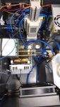
The diy annealer is based on a ZVS 1000W induction heater from Amazon, include some foto's here:
was reading in this forum for a while and it is a great source for information and new idea's! That's why I just registered here.
Hope I will not ask too many stupid questions over time
Speaking about good idea's: Reading this here I couldn't resist and started building my own annealer. Going through all the posts actually I thought that cant be to difficult but now I'm getting a bit crazy ...
The diy annealer is based on a ZVS 1000W induction heater from Amazon, include some foto's here:
Attachments
And here comes the problem:
I use a 48V 750 W power supply, brand new. I know that it needs to be powerd on first and then switching on the ZVS circuit on the 48 V DC side. Here's what happening: The power supply shows 48V -as soon as hooked on it breaks down to around 2V, the fan in the power supply stops rotating and the green LED on the board is flickering. Problem has nothing to do with the relais, I tried with SSR, conventional one and also switch - same result. I checked with a 24V power suplply I had around - same result...
No idea any more, about to order a new ZVS to try this as last option.
Does anyone has an idea how to solve?
Any thought warmly welcome...
And here comes the problem:
I use a 48V 750 W power supply, brand new. I know that it needs to be powerd on first and then switching on the ZVS circuit on the 48 V DC side. Here's what happening: The power supply shows 48V -as soon as hooked on it breaks down to around 2V, the fan in the power supply stops rotating and the green LED on the board is flickering. Problem has nothing to do with the relais, I tried with SSR, conventional one and also switch - same result. I checked with a 24V power suplply I had around - same result...
No idea any more, about to order a new ZVS to try this as last option.
Does anyone has an idea how to solve?
Any thought warmly welcome...
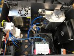
Your build looks fantastic! Well done.
It appears to me that the ZVS board has an issue. The 48V power supply output is hitting the current limit and the voltage is browning out. You could verify with a current meter in series to the ZVS, but given that the same thing happens on a different 24V supply it's not really necessary. The ZVS boards are self resonant, if they get powered up without the work coil present then they don't oscillate and one of the power MOSFET's will just stay stuck on effectively crowbarring the supply. If it stays like that for long enough, the MOSFET will overheat and fail.
You could purchase a replacement MOSFET from Digikey and repair the board if you felt motivated. Q1 or Q2 has likely failed to a short between D-S terminals. a multimeter will show ~ 0 ohm if you measure it out of circuit.
Most of the 1000W Chinese ZVS boards use this schematic, or a close variant of it. If you decide to repair it, then check what MOSFET's are on your board and match them.
Good luck,
Mark
Hi Mark,
thanks a lot for the fast reply. I was already thinking that there must be something wrong with the board but also this one is brand new and I never started it up without the working coil. Anyhow, just found those boards extremely cheap on Amazon here in Germany (by the way in case my english is not so perfect - it's not my first language) and ordered two more (you never know). But I will also try out what you proposed and check if Q1 or Q2 is broken. Should be easy to repair.
Do you think the power supply is ok or do I need a 1000W instead of the 750W?
One more thing is still unclear to me: The coil supplied with the board has all windings of the coil next to each other - direct contact. Is that ok? I saw that some people put an isolaion over the coper wire.
br
Stefan
Similar threads
- Replies
- 11
- Views
- 2K
- Replies
- 7
- Views
- 1K
