The coils should NOT touch...that creates a short in the coil circuit that can destroy your power supply. They don't need to be separated by much, but they need to not touch each other. Also, if a case is inside and against the coil , it short circuits the coils, that is bad also...
Join the Hide community
Get access to live stream, lessons, the post exchange, and chat with other snipers.
Register
Download Gravity Ballistics
Get help to accurately calculate and scope your sniper rifle using real shooting data.

Install the app
How to install the app on iOS
Follow along with the video below to see how to install our site as a web app on your home screen.
Note: This feature may not be available in some browsers.
You are using an out of date browser. It may not display this or other websites correctly.
You should upgrade or use an alternative browser.
You should upgrade or use an alternative browser.
Homemade Induction Annealer
- Thread starter TSloper
- Start date

Hi Stefan,Hi Mark,
thanks a lot for the fast reply. I was already thinking that there must be something wrong with the board but also this one is brand new and I never started it up without the working coil. Anyhow, just found those boards extremely cheap on Amazon here in Germany (by the way in case my english is not so perfect - it's not my first language) and ordered two more (you never know). But I will also try out what you proposed and check if Q1 or Q2 is broken. Should be easy to repair.
Do you think the power supply is ok or do I need a 1000W instead of the 750W?
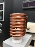
One more thing is still unclear to me: The coil supplied with the board has all windings of the coil next to each other - direct contact. Is that ok? I saw that some people put an isolaion over the coper wire.
br
Stefan
There should definitely be a gap between each coil winding. The coil inductance determines the frequency the ZVS oscillates at and with the windings touching, it will have very low inductance. With that new information, you may find that the ZVS board is still OK and everything may just work once you seperate the coils.
Mark
Hi everybody
was reading in this forum for a while and it is a great source for information and new idea's! That's why I just registered here.
Hope I will not ask too many stupid questions over time
Speaking about good idea's: Reading this here I couldn't resist and started building my own annealer. Going through all the posts actually I thought that cant be to difficult but now I'm getting a bit crazy ...
The diy annealer is based on a ZVS 1000W induction heater from Amazon, include some foto's here:
What did you use for case? Looks super awesome!
What did you use for case? Looks super awesome!
Well, thought a lot about the right case but all I found in electronic/IT supply stores was really expensive. Finally I found this one.
They are used a lot here in Europe for storing /transporting smaller machines like electric saws/ drilling machines etc. they are called Systainer. You can connect them one on each other. One popular wood working machine supplier using them is Festool or Makita.
This particular case is from Auer Packaging.
Hi Mark,Hi Stefan,
There should definitely be a gap between each coil winding. The coil inductance determines the frequency the ZVS oscillates at and with the windings touching, it will have very low inductance. With that new information, you may find that the ZVS board is still OK and everything may just work once you seperate the coils.
Mark
took a bit but now everything is seperated properly. Unfortunately the problem remains. Guess I heave to solder the mosfets out to measure or is it possible while they are in?
Attachments
First, thanks for all you support so far. Now, was just about to solder out the mosfets to measure and had a close look at the board. Really upset now, seems like I got a second hand or so from Amazon. At least somebody worked already on the mosfets !!! Unbelivable. Will return and hope the new ones will solve my problem. Interesting enought - bought the board for 20 € and now the same guy wants 42 €. I'm pretty sure he was aware that is second hand but was sold as new. Online purchase is an adventure....Hi Mark,
took a bit but now everything is seperated properly. Unfortunately the problem remains. Guess I heave to solder the mosfets out to measure or is it possible while they are in?
Attachments
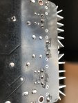
Yeah, that's very annoying!First, thanks for all you support so far. Now, was just about to solder out the mosfets to measure and had a close look at the board. Really upset now, seems like I got a second hand or so from Amazon. At least somebody worked already on the mosfets !!! Unbelivable. Will return and hope the new ones will solve my problem. Interesting enought - bought the board for 20 € and now the same guy wants 42 €. I'm pretty sure he was aware that is second hand but was sold as new. Online purchase is an adventure....
So I have a question. I have a bolt buster I’m guessing since it’s the same concept that I could use that to do this process right? Here is the link to what I have. https://boltbusterinc.com/
The thing works awesome on tractor bolts and rusted bolts underneath trucks. Is it too much for the brass? Thanks.
The thing works awesome on tractor bolts and rusted bolts underneath trucks. Is it too much for the brass? Thanks.
Should work. You'll have to give it a try!So I have a question. I have a bolt buster I’m guessing since it’s the same concept that I could use that to do this process right? Here is the link to what I have. https://boltbusterinc.com/
The thing works awesome on tractor bolts and rusted bolts underneath trucks. Is it too much for the brass? Thanks.
I fried my first power supply because a case got cocked at an angle when it dropped in and shorted out the coil. I use a pyrex welding shield to prevent that now.
Hi guys,
almost desperate in the meantime as I don't get my annealer to work - any help warmly welcome.
Have received two new ZVS 1000W boards and checked them carefully - used that proceedure and found all ok:
Pete's 1000 Watt 12 to 48 Volt ZVS Induction Heater Troubleshooting Guide
But after putting one into the unit - exactly the same problem: Ventilator in the power supply stops and voltage goes down to around 3V, current around 1,6 A. Without a load the unit delivers 48V and the amp meter also shows 1,6A (why actually without a load?)
No idea any more. Do you think the power supply is broken? I posted earlier that I tried already anoher one with 24 V but that one had only 5A I just noticed - so maybe that test was not representative as to low in power.
The power supply I use is a 750w 48V, have no alternative load to check it. Just tried with one 220V 100W light bulb, that works.(glowing gentle only)
Really lost now...and hoped to have it up and running before x-mas....
Attachments
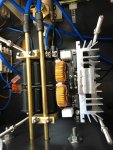
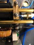
As you can see on the picture I made two more stable connectors between board and could. Used brass for this - so should be all fine. That's actually the only thing I modified beside the coil.
Can the board be tested without the coil or will is destroy the board? That's something I could still do.
Can the board be tested without the coil or will is destroy the board? That's something I could still do.
With your wiring, the blue wire is positive and black negative? Is the right hand tube on the coil touching on your new connecter, it looks really close in the photo:As you can see on the picture I made two more stable connectors between board and could. Used brass for this - so should be all fine. That's actually the only thing I modified beside the coil.
Can the board be tested without the coil or will is destroy the board? That's something I could still do.
With your wiring, the blue wire is positive and black negative? Is the right hand tube on the coil touching on your new connecter, it looks really close in the photo:
View attachment 7504260
Yes, the blue is negative, the black positive. Add one photo to show there is a gap.Looks close but just on the foto - there is a 3mm gap inbetween.
Attachments
What type of power supply are you using? 1.6A is very low when connected to the ZVS, and very odd the voltage is folding back at such low current. You haven't inadvertently applied a current limit on the output have you? my coil needs about 4-5A @ 42V just to energise an empty coil.
Thanks for all your patience with me.
Finally I found the reason! Now it is clear but I never thought about it before. On the photos you can see that I build a little aluminium block holding the thermo element I put in to be able to see the temperature of the Mosfet cooler. Well, that alone is maybe a good idea but not fixing the block to both Mosfet coolers!!! That was the short I couldn't find.
Now it is heating the brass in seconds - great!
Almost done with mine. Still have parts on the way for an auto drop/ eject for a stand that has yet to be attached to the case. I also plan on adding a IR beam proxy switch for an auto mode. Right now I wired in the integrated computer case momentary switch for a trigger, running 5v for that from an old spare computer PSU. That PSU is also running some fans on the 12v line.
TSloper, so to check, run pin gauge through new and annealed brass AFTER its been run through mandrel ??No, I'm using a RCBS FL SB die without the expander ball. The mandrel is a 21st Century SS mandrel and made a huge difference in neck runout over the expander ball. The mandrel does take care of that spot when the mandrel is in the neck. However, the hardness of the brass is greater there at that junction than the rest of the neck and is springing back when the mandrel is removed. This brass had 4-5 firings and was annealed each time so I know that my annealing was not adequate. It was close but not close enough as indicated by the hard stop of the pin gauge at that location. The pin should pass with a light drag. To get it to pass I would have had to put considerable force on it. I tested multiple pieces of that same batch after tweaking the annealing time/voltage and they all passed the pin correctly with a drag comparable to brand new pieces of the same lot sized the same way (minus annealing).
As I mentioned in an earlier post... it is obvious when you have over annealed the neck. The same pin gauge that drags correctly on new brass will basically fall through on an over annealed neck after being run through the mandrel phase. The springback is gone which is not what you want.
Tim,
Just finishing up on annealer, nice write up,thanks. Just checking to see if you recall what screws you used on the bling but on the powder supply for mounting it.
John
Just finishing up on annealer, nice write up,thanks. Just checking to see if you recall what screws you used on the bling but on the powder supply for mounting it.
John
Hi folks, i have a working version of 24v/20a annealer with a manual on/off switch thanks to all the posts on this forum. I’m getting good temps in short times for 308 and 7mm but need more precision on timing to make this totally repeatable. I am trying to add the sestos b3s timer into my circuit as many of you have done. Sadly, i cannot figure out the wiring. does anyone have a super simple diagram or picture of wiring sestos b3s with a momentary switch? I’m only using the one-shot mode, so it’s the easiest possible setup.
I am trying to add the sestos b3s timer into my circuit as many of you have done. Sadly, i cannot figure out the wiring. does anyone have a super simple diagram or picture of wiring sestos b3s with a momentary switch? I’m only using the one-shot mode, so it’s the easiest possible setup.
There is usually a sticker on the side of the timer with a wiring diagram...I found it to be useful. If your unit does not have a sticker, check the page where you ordered it for a pic with it.
Here's the one I got with a pic of the diagram:

Sestos C2S-R-220 Digital Switch Timer - Black for sale online | eBay
Find many great new & used options and get the best deals for Sestos C2S-R-220 Digital Switch Timer - Black at the best online prices at eBay! Free shipping for many products!
www.ebay.com
Thank you. I do have that diagram, but i haven’t been able to correctly wire it. I don’t really understand what I’m doing wrong. I can get the power to turn the thing on using 9 and 10 pins and i can short the 1 and 2 pins to make the timer run. But i can’t get the NO relay to close when the timer starts or when it stops or anything. I’m clearly missing something important about how the circuit is supposed to work. Sorry this is such a basic question.There is usually a sticker on the side of the timer with a wiring diagram...I found it to be useful. If your unit does not have a sticker, check the page where you ordered it for a pic with it.
Here's the one I got with a pic of the diagram:
Sestos C2S-R-220 Digital Switch Timer - Black for sale online | eBay
Find many great new & used options and get the best deals for Sestos C2S-R-220 Digital Switch Timer - Black at the best online prices at eBay! Free shipping for many products!www.ebay.com
If you have the same version of timer (four timers and two relays), then the A relay will close/open during timer 1, then during timer 2 nothing happens (except the timer counts off), then during timer 3 the C relay will close/open, and lastly, during timer 4 it just counts off.Thank you. I do have that diagram, but i haven’t been able to correctly wire it. I don’t really understand what I’m doing wrong. I can get the power to turn the thing on using 9 and 10 pins and i can short the 1 and 2 pins to make the timer run. But i can’t get the NO relay to close when the timer starts or when it stops or anything. I’m clearly missing something important about how the circuit is supposed to work. Sorry this is such a basic question.
For example:
Timer 1 counts down 3.2 seconds while closing the A relay (or opening it, depends which function you need)
Timer 2 counts a delay (only a short one is needed)
Timer 3 counts down 0.5 seconds while closing the C relay (or opening it) - triggers the case drop solenoid
Timer 4 counts off (as a delay before starting cycle over for placing a new case in coil
For the relay contacts, you are powering the component from another source (ie 12 volt supply) by connecting it to the COM contact and then connect the output from the NO (normally open) contact (it you want it to turn component on) to the actual component (ZVS board or drop solenoid) you need to power. You are not using the AC power put into the timer. The timer only controls the relay to switch another power source on or off.
If you are using the timer to turn something off, then you would use the COM and NC (normally closed) contacts so that the component is powered except when the timer controlling that relay is running.
Sorry if this is long winded, overly simplified/complicated, or redundant...
Last edited:
Sir I would like to utilize Batteries ( 2 each 12vdc in series 24vdc ) as the Main Power Supply...would that be ok ?
David Maio
512-293-2140
David Maio
512-293-2140
I've got my new annealer just about sorted, I'm just waiting on a closed loop stepper to arrive for the case feeder. It really cranks the cases through! Heating is amazingly well controlled, have a look at the Tempilaq on the cases at the end of the video.
I've got my new annealer just about sorted, I'm just waiting on a closed loop stepper to arrive for the case feeder. It really cranks the cases through! Heating is amazingly well controlled, have a look at the Tempilaq on the cases at the end of the video.
Impressive setup!! Looks & works fantastic
Can you share more about the case feeder and your coil winding?
The case feeder is a work in progress, I've had it going but wanted to run it off the arduino as well so it's got feedback of its position. Most of it is 3d printed currently, this is about the 5th prototype. Another week or 2 and I'll give a full rundown.Impressive setup!! Looks & works fantastic
Can you share more about the case feeder and your coil winding?
The coil is 3mm copper tube, The first one was 7 1/2 coils around a 28mm mandrel. This one is still 7 1/2 but double wound to make it shorter. I slid the insulation on first then wound the first few coils around a mandrel and the outer ones around the inner then opened them up a little so they weren't touching. It works much better with short cases like the BR.
The coil has coolant pumped through to cool it and a little radiator at the rear of the machine. It uses one of the ZVS boards, a solid state relay and a 48v 1000W power supply controlled by an MGNZ Arduino control board.
The case feeder is a work in progress, I've had it going but wanted to run it off the arduino as well so it's got feedback of its position. Most of it is 3d printed currently, this is about the 5th prototype. Another week or 2 and I'll give a full rundown.
The coil is 3mm copper tube, The first one was 7 1/2 coils around a 28mm mandrel. This one is still 7 1/2 but double wound to make it shorter. I slid the insulation on first then wound the first few coils around a mandrel and the outer ones around the inner then opened them up a little so they weren't touching. It works much better with short cases like the BR.
The coil has coolant pumped through to cool it and a little radiator at the rear of the machine. It uses one of the ZVS boards, a solid state relay and a 48v 1000W power supply controlled by an MGNZ Arduino control board.
View attachment 7575467
NIce and I see you are a tidy man! I'm also using the MGNZ board and really happy with the setup. I still have the single wound 7 1/2 coil. I have to anneal 6.5CR, .308 win and 300 NormaMag so I'm wondering if the double wound would work also good for the larger callibers.
I have a 3d printer so'm definitely interested in the feeder when you are ready to share.
Are you planning to run the case feeder from the MGNZ board or do you plan to use a separate Arduino for that?
The plan is to run it from the same board but with a separate power supply. Happy to share the files for the feeder once I have it up and running properly.NIce and I see you are a tidy man! I'm also using the MGNZ board and really happy with the setup. I still have the single wound 7 1/2 coil. I have to anneal 6.5CR, .308 win and 300 NormaMag so I'm wondering if the double wound would work also good for the larger callibers.
I have a 3d printer so'm definitely interested in the feeder when you are ready to share.
Are you planning to run the case feeder from the MGNZ board or do you plan to use a separate Arduino for that?
I am still sourcing parts. I havent had time work on it, since work has been super busy due to Covid.
I found this thread after I'd decided that I wanted to try building an induction annealer and signed up for the forum so I could see the pictures people have posted. I was about halfway through figuring out the program for a really simple Arduino run annealed when I saw MGNZ's excellent writeup and shamelessly decided that was probably the way to go. I had an old computer that I decided to gut and use the case as well as the power supply, and I've got it nearly done now. I have a seperate 42v 1200w supply running the zvs board, so the PC supply is only used for powering the Arduino and cooling fans. A bit overkill, but it was there. I ran most of it on the bench to make sure it would actually work before mounting anything in the computer case, hopefully I don't run into any cooling issues once it's all enclosed. I still have to mount the Arduino board and the radiator, plus a little more wiring, but I'm hoping I'll be able to get it running this weekend.


Kristian
Kristian
Very nice. I will say that if you are automating and running many cases with that RC servo drop (love it by the way) you will really want to consider water cooling the coil quickly. Fans towards the heatsinks will also help you out. These parts do get warm when doing many cases in mine.I found this thread after I'd decided that I wanted to try building an induction annealer and signed up for the forum so I could see the pictures people have posted. I was about halfway through figuring out the program for a really simple Arduino run annealed when I saw MGNZ's excellent writeup and shamelessly decided that was probably the way to go. I had an old computer that I decided to gut and use the case as well as the power supply, and I've got it nearly done now. I have a seperate 42v 1200w supply running the zvs board, so the PC supply is only used for powering the Arduino and cooling fans. A bit overkill, but it was there. I ran most of it on the bench to make sure it would actually work before mounting anything in the computer case, hopefully I don't run into any cooling issues once it's all enclosed. I still have to mount the Arduino board and the radiator, plus a little more wiring, but I'm hoping I'll be able to get it running this weekend.
View attachment 7595288
View attachment 7595291
Kristian
Thanks. Yes, water cooling the coil is in the plan, I just don't have the radiator or fan mounted in the picture yet. I'm going to put the radiator and fan pulling air out the side of the case near the heatsinks of the zvs board, and if that doesn't give enough air flow I'll add a second fan pulling cool air from the top of the case down across the board and towards the radiator.Very nice. I will say that if you are automating and running many cases with that RC servo drop (love it by the way) you will really want to consider water cooling the coil quickly. Fans towards the heatsinks will also help you out. These parts do get warm when doing many cases in mine.
Kristian
As much as I wanted to get everything in the old computer case I've got, I don't think it's going to happen. It all fits, but there seems to be too much electrical interference from the power supplies and the zvs board being right beside the Arduino. I tried running it all in the case, and it keeps having weird glitches, which don't happen when I've got the power disconnected from the zvs board. I also managed to cook my solid state relay, so I think I'm going to have to build a box of some sort that won't be quite as crowded. Back to the drawing board I guess.
Kristian
Kristian
In mine I have the Arduino mounted directly below the ZVS board and it hasn't been an issue. There is a 3mm aluminium shelf between the two though which might have made a difference. Are you sure you don't have a fault on the board? A short might be what killed your relay?As much as I wanted to get everything in the old computer case I've got, I don't think it's going to happen. It all fits, but there seems to be too much electrical interference from the power supplies and the zvs board being right beside the Arduino. I tried running it all in the case, and it keeps having weird glitches, which don't happen when I've got the power disconnected from the zvs board. I also managed to cook my solid state relay, so I think I'm going to have to build a box of some sort that won't be quite as crowded. Back to the drawing board I guess.
Kristian
In mine I have the Arduino mounted directly below the ZVS board and it hasn't been an issue. There is a 3mm aluminium shelf between the two though which might have made a difference. Are you sure you don't have a fault on the board? A short might be what killed your relay?
View attachment 7599311
Does your 40A DC solid state relay tend to get hot and require the heatsink? Looks like these units are about $10 here without a heatsink.
My good old ca-chunk relay has worked fine for ~1k cycles I would estimate, but just recently it is not closing immediately upon cycle start. In typing this I now realize I need to stick a meter on it and see if it is getting the close signal from my controller as the problem could lie there, but I still suspect the relay first.
I'll play with mine a bit more to see if I can get it working better. I wonder if maybe some shielding on the wiring would help? I definitely need to clean up my wiring a bit, and should probably ground my power supply to the case too.
Kristian
Kristian
I'm not sure, I've never checked. I ordered the heatsink because I thought there must be a reason they make them for the relay but it's worked fine since I put it in there. It even copped being wired backward at first and just stayed open from memory. I bought the relay locally because the one I ordered from O/S didn't turn up. It was around $100 with the heatsink which was a lot more expensive, not sure that means it's better.Does your 40A DC solid state relay tend to get hot and require the heatsink? Looks like these units are about $10 here without a heatsink.
My good old ca-chunk relay has worked fine for ~1k cycles I would estimate, but just recently it is not closing immediately upon cycle start. In typing this I now realize I need to stick a meter on it and see if it is getting the close signal from my controller as the problem could lie there, but I still suspect the relay first.
Don't ground the DC- to the case. I have the earth for the AC power going to the case as well as the PS. Have a good look at your coil and make sure the coils are not touching each other as well, that'll cause all sorts of issues and mess up the relay.I'll play with mine a bit more to see if I can get it working better. I wonder if maybe some shielding on the wiring would help? I definitely need to clean up my wiring a bit, and should probably ground my power supply to the case too.
Kristian
Thanks Gtar, I think I found my weird interference issue. I had one of my connections to the display that was sort of touching the metal case, right near where the induction coil comes out. I pulled that back and it seemed to work fine, at least until it ate my spare solid state relay. This time I had it mounted to a small heatsink and sitting in front of the radiator fan. I've got my supply turned up to 53V, but it's only drawing 5.4A with the coil empty, 6.6-6.8A with a 308 case in the coil. With the lights out I can see a hint of glow at 3.8 seconds, so I think the 1200 W power supply I bought is massively overkill. I could easily get away with a 600W supply, and that might gain me enough space for a bigger heatsink and another fan if I try another solid state relay. If your more expensive solid state relay is working well, I'm going to say it's better than the two cheap ones I've toasted just trying to get mine sorted out. I've used them at work with much higher current loads, and never had this much trouble. We were running solar powered pumps that would have a start current of around 25A @ 28-30V, they would run for about 5 seconds a minute on continuous duty. Too bad I no longer work there.
Kristian
Kristian
Last edited:
I think the reason for the low current is the coil size you are running guessing from the picture.Thanks Gtar, I think I found my weird interference issue. I had one of my connections to the display that was sort of touching the metal case, right near where the induction coil comes out. I pulled that back and it seemed to work fine, at least until it ate my spare solid state relay. This time I had it mounted to a small heatsink and sitting in front of the radiator fan. I've got my supply turned up to 53V, but it's only drawing 5.4A with the coil empty, 6.6-6.8A with a 308 case in the coil. With the lights out I can see a hint of glow at 3.8 seconds, so I think the 1200 W power supply I bought is massively overkill. I could easily get away with a 600W supply, and that might gain me enough space for a bigger heatsink and another fan if I try another solid state relay. If your more expensive solid state relay is working well, I'm going to say it's better than the two cheap ones I've toasted just trying to get mine sorted out. I've used them at work with much higher current loads, and never had this much trouble. We were running solar powered pumps that would have a start current of around 25A @ 28-30V, they would run for about 5 seconds a minute on continuous duty. Too bad I no longer work there.
Kristian
If you read a good way further back I went through a couple coils and settled on one that is quite a bit smaller ID than what yours appears to be. You'll get a much faster annealing time and you can make use of that 1200w supply.
Yes, I saw a few different coil sizes being used here. I made mine based on MGNZ's website, but had already ordered the 1200 watt supply. Quite a few people seemed to have had good success with the coil dimensions I used, about 1 1/8" inside diameter. How much quicker are you able to heat the case? Under 4 seconds seems pretty quick to me, but I've never played with one of these before. I guess the quicker it heats the case, the less time there is for the heat to get to the case head.I think the reason for the low current is the coil size you are running guessing from the picture.
If you read a good way further back I went through a couple coils and settled on one that is quite a bit smaller ID than what yours appears to be. You'll get a much faster annealing time and you can make use of that 1200w supply.
Kristian
My supply is 600w max, and I have turned the voltage down from the nominal 48v to avoid over-current protection, but on something like R-P .260Rem brass I can get it to a dull glow with a dark room in 4s or so. Lapua takes longer from my experience with my specific setup. I need a larger power supply to make use of what I have, so for now the lower voltage (~40v) with this coil keeps me from tripping the unit at 12.5A and allows acceptable annealing time / results across my range of .300BLK, .204 Ruger, .223, .260, .308, 300 PRC. Lots of balancing / juggling to get it running well but it seems to work great once the sweet spot is found.Yes, I saw a few different coil sizes being used here. I made mine based on MGNZ's website, but had already ordered the 1200 watt supply. Quite a few people seemed to have had good success with the coil dimensions I used, about 1 1/8" inside diameter. How much quicker are you able to heat the case? Under 4 seconds seems pretty quick to me, but I've never played with one of these before. I guess the quicker it heats the case, the less time there is for the heat to get to the case head.
Kristian
Similar threads
- Replies
- 11
- Views
- 2K
- Replies
- 7
- Views
- 1K
