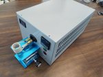
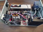
I think I digested, like, 85 pages of thread on the accurateshooter.com forum about the annealer design I chose before I started ordering stuff. Ha ha. One thing I learned was exactly what you found - without some form of current control, folks had to make adjustments in case insert depth, etc, to avoid drawing too much current. The initial design over there uses a slightly different coil dimension (1/8" copper tube, 8 turns at 1" ID). Most of them were using 600w supplies. A couple folks started picking up on bigger supplies and ones that support current control as a way to shorten annealing times and also prevent the supply from being overloaded. A couple folks roasted induction boards, too, because they had a power supply that will deliver more than the 1000w rating, and the board will suicide itself with enough power. So, 750w seemed like a good sweet spot.
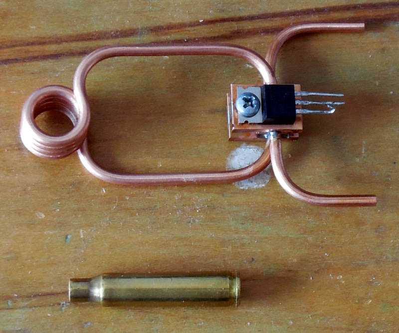
Later, I wound a smaller coil (same material, 8 turns at 3/4" ID), and that allowed me to use the full capability of my power supply.
Sounds like you've balanced it out - as long as you're not getting too much heat into the body of the case, you're GTG.
That could work... it could also release the magic smoke from one or both supplies - and at 1200w potential, you could also nuke your induction board (it's still a 1000w board, right?). But, it's definitely an interesting thought. I'll have to research that option a little more - parallel voltage sources can behave kind of strange, as I understand them.


 Why not start there and see if it works, first?