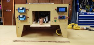
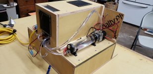
Built my annealer in the fall. MGNZ makes board. The documentation on that firmware isn't great. It's OK, but I've had to bang my head on a lot of things to tweak it and understand why things were doing what they were and how the wiring needed to be. So, if anyone has questions, lmk, maybe I can help. Like, I had to get additional 5v power in my servo because what the board supplied wasn't enough.
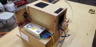
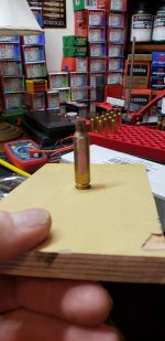
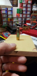
Here's how I did my trap door. Designed my own platform. It's cracked, because I need to adjust some tolerances on the linear bearings. The trap door itself is high temperature G7 (like g10 but high temp).
And here's an example of it working. I've since tweaked it to run smoother. Had the timing off a bit here. I'm using a Teflon block in the middle so the cases don't melt the 3d printed plastic.
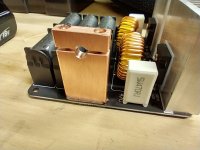
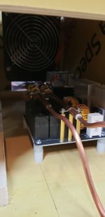
Couple of things for anyone to consider. First, the ZVS boards from Amazon are not made for their rated wattage, imo. I'm using a Meanwell 1000w 48v PSU. It will do its rated power. The 1000w ZVS board can barely accept 12ga wires on the inputs. The output clamps are flimsy and I'm roasting them. The capacitors overheat after about 15 cases or so. I've measured my voltage and amperage, and I'm full send... I'm getting roughly 25 amps at 42v (voltage sag) under load.
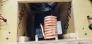
Second, coils. I've found 1/8 copper to be insufficient, not because of its current carrying capacity, but you get almost no water flow through it with a 12v pc pump. It's just too much restriction. When I run several cases in a row, I'm starting to get vapor in my cooking lines. I'm moving to 3/16 to see if that improves.
Lastly, some of the MGNZ makes stuff isn't up to 1000w. The amp sensor says 30a, but it won't accept wires large enough to handle more than 10a. I got a dfrobot 50a sensor instead. I'm actually considering just scrapping the MGNZ board and doing my own with better display, sensors, and controls, but at this point, I've probably got it working well enough that it's not worth it to improve.
I am currently in the process of building my own ZVS board. Look at Schematix on YouTube and his website. He's got a design for a 1.4kw ZVS board that is much more robust. I'm going to use 10 capacitors to help with power dissipation. Need to recalculate my coil for that and the larger tubing. I'm going to use copper grounding lugs for the tube connectors. Should be much more robust and allow for basically continual use.