• Watch Out for Scammers!

    We've now added a color code for all accounts. Orange accounts are new members, Blue are full members, and Green are Supporters. If you get a message about a sale from an orange account, make sure you pay attention before sending any money!

Homemade Induction Annealer

Sitting on grains of (dirt) something you can see under there.

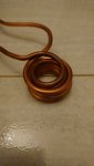
The color change looks normal on that case on the right even if meaningless in the long run.

Looks a lot like the same ammount as on starline when I get some of it.
 
Last edited:
Yea the color seems appropriate. I'm wondering how I should go about testing times and temps. How far down should I take the heat on the case, IE how long should I leave it in the coil.
 
So many variables.

In the old days cases were set in a pan of water templaqe applied lights dimmed and a hand held torch.

Shown to me in 1982 ish by an old bench rest guy.

Much better these days.
 
So many variables.

In the old days cases were set in a pan of water templaqe applied lights dimmed and a hand held torch.

Shown to me in 1982 ish by an old bench rest guy.

Much better these days.

Yea i used the old drill/propane torch method. I still do with my nickel 223 brass. But I just have a desire to try new things and expirement.

Any input on how to test/document some annealing?

I was thinking of having non annealed, and a few different temps of annealing to see how they size and how they maintain neck tension/accuracy
 
I've been building one based on this thread out of my old computer tower.

I ran into an issue when my water reservoir leaked, otherwise it would be pretty close to ready to anneal.

Here's what I've done so far on it. Once I figure out a new reservoir, hopefully I'll be able to hook it up and test it out on some brass.

 
  • Like
Reactions: ManOfAction
I've been building one based on this thread out of my old computer tower.

I ran into an issue when my water reservoir leaked, otherwise it would be pretty close to ready to anneal.

Here's what I've done so far on it. Once I figure out a new reservoir, hopefully I'll be able to hook it up and test it out on some brass.


Good luck with the reservoir, looks like it's coming together nicely though. Why did you go with that particular power supply supply? Seems like its specs are 24V-17A-400W? I was thinking of upgrading from my 48V-12.5A-600W supply to a 48V-15.7A-750W one.
 
Good luck with the reservoir, looks like it's coming together nicely though. Why did you go with that particular power supply supply? Seems like its specs are 24V-17A-400W? I was thinking of upgrading from my 48V-12.5A-600W supply to a 48V-15.7A-750W one.

I have the same 48v 12.5a supply and this board would benefit greatly having the additional current available.
 
Good luck with the reservoir, looks like it's coming together nicely though. Why did you go with that particular power supply supply? Seems like its specs are 24V-17A-400W? I was thinking of upgrading from my 48V-12.5A-600W supply to a 48V-15.7A-750W one.

Thanks! Actually in the hospital now after a new baby, so hopefully I'll get some time when we get home while momma and baby are resting to put the reservoir together!

I was just trying to imitate what @TSloper did. The power supply he linked wasn't available when I ordered, so I went with the next size up that I could find. I also don't remember perfectly without looking it up again, but it seems that some of the components (timer?) were only rated up to 36v.

I know there was some discussion about those bigger power supplies in this thread. The impression I got was that if I kept the diameter smaller, I didn't need as big of a power supply. I could be way off on saying that. It's been probably about 10 years since I messed around with inductance calculations, so I'm fuzzy on the math. Instead, I'm just trying to imitate and adjust.
 
  • Like
Reactions: Westwood
just found this thread after wondering the same thing as everyone else, surely i could build my own annealing machine :) as ones on market are way overpriced.
bought all the components, no i wait for the post man to deliver. I hope though to reuse the copper pipe that comes with my unit and rewind the coil, as i do want to make it water cooled, so will see how that goes in the future. worst case if i screw it could buy the 8awg wire and wind as per op

The coil it ships with is 1/4" tubing and was too large for me to shape into a properly sized coil. My Oreilly auto parts had 1/8" and 3/16" copper tubing which worked well for winding smaller coils.
 
  • Like
Reactions: metallurgist
The coil it ships with is 1/4" tubing and was too large for me to shape into a properly sized coil. My Oreilly auto parts had 1/8" and 3/16" copper tubing which worked well for winding smaller coils.

oh thanks i will take a look locally for some if that is the case, did you have your specs on number of winds and internal diameter of coil?
 
oh thanks i will take a look locally for some if that is the case, did you have your specs on number of winds and internal diameter of coil?

First coil .6" inside diameter, 9.5 turns from 1/8 tubing - Very efficient, also power hungry. My power supply does not have enough current capacity. Post #63 in this thread.

Second coil 0.75" ID, 8.5 turns from 3/16 tubing - Works very well with my power supply for .223 through .308 cases. Have not tried larger on this coil. Post #67 in this thread.

Which power supply do you have
 
Which power supply do you have

48v 12.5a Meanwell 600w

At 48v the setup wants to draw more than 12.5a and trips the supply with larger cases.

With my larger coil and the supply turned down to its minimum 39v, I can anneal .308s non stop without overcurrent protection kicking in.
 
  • Like
Reactions: jcal73
Over the last couple of days I put together an induction annealer setup. All components minus the coil were sourced from Amazon. I turned the coil myself from solid copper wire to ensure proper inductance and distance to the case. The power supply is 24V/15A. Switching frequency of the induction coil is ~120 kHz. The coil supplied with the ZVS unit was far too large in diameter and would not sufficiently heat the brass with the 24V/15A supply. Proper coil sizing is key. I have not found a need for any additional cooling.

Tim

I am starting to out one of these together now, I have a couple questions, after using for a little while are there any changes you would or have done? Also when you made a new coil what did you make the ID?

Thank you,
Russell
 
I am starting to out one of these together now, I have a couple questions, after using for a little while are there any changes you would or have done? Also when you made a new coil what did you make the ID?

Thank you,
Russell

I would go with a larger power supply. I went with the 24v but I feel like I could go faster. As it sits now, I'm annealing a 308 in about 8 seconds. I'm going to try a new coil. I wrapped mine around a 1/2 socket extension. I may try with 1 or 2 less wraps.
 
Awesome build, this may save me from more "honey-do" projects until we get let out of time-out here.
 
@metallurgist , are you a metallurgist ? do you have access to a hardness tester?

I am a metallurgist.

I do not have access to a hardness tester unfortunately, especially a Vickers. (n)

Briefly looking at what AMP has published, their data seems pretty good. I need to dig a little deeper into it though.
 
It appears that the height of the brass within the induction coil is important.

This is 308 brass at various times and two different heights.

The high set holds the brass higher within the coil causing it to have more brass within the coil.

The mid set has the top of the brass just above the middle of the coil which reduces the amount of brass in the coil.

This is appearing to concentrate the power to the neck and not put as much heat into the body.
 

Attachments

  • IMG_20200524_225822~2.jpg
    IMG_20200524_225822~2.jpg
    667 KB · Views: 296
  • IMG_20200524_230447~2.jpg
    IMG_20200524_230447~2.jpg
    399.1 KB · Views: 318
It appears that the height of the brass within the induction coil is important.

This is 308 brass at various times and two different heights.

The high set holds the brass higher within the coil causing it to have more brass within the coil.

The mid set has the top of the brass just above the middle of the coil which reduces the amount of brass in the coil.

This is appearing to concentrate the power to the neck and not put as much heat into the body.

I run my brass about half way into the coil. Shove too much in and it draws excess current heating the body like you are finding.

The further you insert it, the more current it is also going to draw.
 
  • Like
Reactions: metallurgist
I am no EE either. That is why I didn't consider how high the current might be at 48V. 600W sounded like plenty of power, until Tsloper helped me build an efficient coil haha.

I think just reducing the output voltage will just slow my heating times, and may cause further trouble on .308 and .260 cases. With the 3/16 tubing coil in place that he specced out I am able to successfully anneal .204 ruger up to .308win. the 3/16 tubing coil may be less efficient than the smaller 1/8 tubing coil for those case sizes, but it does allow for 12.5a or less draw with the supply at ~38v when doing .308.

If I were doing it over I would just buy a 48V 1000w supply. If I were to upgrade now I would just buy a matching 600w supply, set the voltages independently, and then wire them in parallel.

Hi. Let me see if I understood your comment: if I use 1/8 tubing instead of 3/16, will it be better for 48V to aneall 308 brass?
I'm facing huge problems with high current (over 20A at 48V), and I'm using 3/16 copper tube. I already made a bunch of coils, with many different setups and none got good enough.... Can you help me with something? Thanks in advance!
 
48v 12.5a Meanwell 600w

At 48v the setup wants to draw more than 12.5a and trips the supply with larger cases.

With my larger coil and the supply turned down to its minimum 39v, I can anneal .308s non stop without overcurrent protection kicking in.
I'm using a 48V 20A and still getting over current! What am I doing wrong?
Trying to find the best coil, none of them worked properly. Neither with large or smaller id, or more os less turns.
I have only 3/16 copper tube here (didn't find any place with the 1/8). I wonder you could advice me something!
Thanks

How much of the brass is in the coil? I place the top of the neck about half way into the coil. You can put less in the coil to reduce current.

Is your voltage adjustable? The lower your voltage, the less current it will draw.

Are you able to measure actual current? Or just tripping the supply?
 
I was thinking the same.

From my small experiment, a wrap or two of height in the coil can make a big difference.
 
How much of the brass is in the coil? I place the top of the neck about half way into the coil. You can put less in the coil to reduce current.

Is your voltage adjustable? The lower your voltage, the less current it will draw.

Are you able to measure actual current? Or just tripping the supply?
Testing with no brass is between 18 / 19A. If I just run twice, the coil starts to heat then the current starts to increase too. As heating increases, current increase too.
My power supply is fix. No way to adjust it! And it has a protection circuit, that deacrease a little the voltage (automaticaly)in order to limit the current at its maximum (20A). But if works too high, it will blow the protection fuse.

I'm thinking to develop a doble layer coil, trying to increase its inductance and keep the lenght short. My actual coil has 9 turns of 3/16... it is very long!

My project was very well designed! Including with my own control circuit and many parts many in 3D printer. Also, the "release door" for the cases I made it with a servo motor, instead of a solenoid. Works very smooth and precisely, with some sensor to detect the presence of the brass at the tray.

*** I just tested now another coil I had tested with the 24V supply. It was the best setup till now, with my 48V supply, but still give me over current (20A) but not it's making smoke with only 3.5 seconds. I'll do another doble layer coil, with 1 and with 2 more turns and see how it works. At least, with 3/16 tube, this coil keeps with smaller lenght.
* Please don't consider this coil the best made, hahaha.... was one of my first made, so not that good as the last units
 

Attachments

  • IMG-20200525-WA0044.jpeg
    IMG-20200525-WA0044.jpeg
    284.8 KB · Views: 275
  • DSC_5171.JPG
    DSC_5171.JPG
    218.8 KB · Views: 256
Last edited:
Testing with no brass is between 18 / 19A. If I just run twice, the coil starts to heat then the current starts to increase too. As heating increases, current increase too.
My power supply is fix. No way to adjust it! And it has a protection circuit, that deacrease a little the voltage (automaticaly)in order to limit the current at its maximum (20A). But if works too high, it will blow the protection fuse.

I'm thinking to develop a doble layer coil, trying to increase its inductance and keep the lenght short. My actual coil has 9 turns of 3/16... it is very long!

My project was very well designed! Including with my own control circuit and many parts many in 3D printer. Also, the "release door" for the cases I made it with a servo motor, instead of a solenoid. Works very smooth and precisely, with some sensor to detect the presence of the brass at the tray.

I would be keen to see how the servo drop works, if you would like to share please? setup looks very clean and neat
 
I would be keen to see how the servo drop works, if you would like to share please? setup looks very clean and neat


Sorry, but I don't like to keep posting my things on youtube! But there is a Dropbox link so you can see it.
;)

* My display doen't flick like it is at the video. That is my camera in different frequency. It works smooth and I used Arduino for the whole project and SSR direct current 60A to activate the ZVS.
 
  • Like
Reactions: BPortelli
Testing with no brass is between 18 / 19A. If I just run twice, the coil starts to heat then the current starts to increase too. As heating increases, current increase too.
My power supply is fix. No way to adjust it! And it has a protection circuit, that deacrease a little the voltage (automaticaly)in order to limit the current at its maximum (20A). But if works too high, it will blow the protection fuse.

I'm thinking to develop a doble layer coil, trying to increase its inductance and keep the lenght short. My actual coil has 9 turns of 3/16... it is very long!

My project was very well designed! Including with my own control circuit and many parts many in 3D printer. Also, the "release door" for the cases I made it with a servo motor, instead of a solenoid. Works very smooth and precisely, with some sensor to detect the presence of the brass at the tray.

That sounds like a very high current for no load. Are any of the coils touching each other? There should be some clearance the whole way.

Your coil also looks larger, my coil from 3/16 is 0.75" / 19mm inside diameter. I'm not an engineer so I don't know how the diameter relates to idle current draw, but the smaller coil I have draws much higher current when using the same brass
 
  • Like
Reactions: TSerrao

Sorry, but I don't like to keep posting my things on youtube! But there is a Dropbox link so you can see it.
;)

* My display doen't flick like it is at the video. That is my camera in different frequency. It works smooth and I used Arduino for the whole project and SSR direct current 60A to activate the ZVS.
Thanks for the video link, has given me a few ideas how to do mine, once parts turn up
Cheers
 
  • Like
Reactions: TSerrao
That sounds like a very high current for no load. Are any of the coils touching each other? There should be some clearance the whole way.

Your coil also looks larger, my coil from 3/16 is 0.75" / 19mm inside diameter. I'm not an engineer so I don't know how the diameter relates to idle current draw, but the smaller coil I have draws much higher current when using the same brass
I saw the same. Smaller coils, increases current. So in my project, which has high current with no load, always give me over current as soon as I put a single mm of brass at the coil center.

I just post my other tested coil. Double layer, 4 + 4 turns. By the way, none of my coils have shorted any ring (touching). I made my own tools at 3D printer to made perfect coils and with the same pitch and the same rounded axial body. So, about problem with this, the chance is zero, hehehe!

I'll try to make another double layer coil, with one more turn. This last test gave me almost lower than 20A, but still going over. With no load, now I got 15A. Which is good! Almost there!

Are your current directions the same or counter in your double coil?
 
Are your current directions the same or counter in your double coil?
I made the same question to myself when I was reading about double coils. As far as you don't change the TURN DIRECTION, you can go up and down while turning. Like radio coils, with too much turns, it's impossible to turn just to one way (up or down), but turns always to the same turn direction (axial meaning).
I don't know how to explain, hehehe, but that's it. It works!

Check this video out. This man made many multiple layers coils to test.

 
  • Like
Reactions: metallurgist
I made the same question to myself when I was reading about double coils. As far as you don't change the TURN DIRECTION, you can go up and down while turning. Like radio coils, with too much turns, it's impossible to turn just to one way (up or down), but turns always to the same turn direction (axial meaning).
I don't know how to explain, hehehe, but that's it. It works!

Check this video out. This man made many multiple layers coils to test.


(y)

I had an idea that with the double coils, maybe counteracting magnetic fields could be driving the current way up. But it sounds like current flow is in the same direction which I wouldn't think would do that.
 
I ran my setup with a fairly high duty cycle tonight. The thermocouple I have on the back of my heat sink for the ZVS board got up to 127 degrees. It really leveled out once it got to about 118 though, so it took some pretty consistent cycling to get the extra 9 degrees. Ambient was about 73 which my water and pump seemed to stay at without issue. I do have a fan pulling air up across the board, too. Overall, that temperature rise doesn't seem unreasonable, and it would fall pretty quickly with short stops.
 
  • Like
Reactions: TSerrao
Another thing to mention that I nearly forgot...

While testing I noticed that the metal computer case where the coil passed through was becoming warm, so that is why you'll note my case panel is cut out with most everything being replaced with plywood and MDF. It is probably a small effect, but I imagine there is a small additional power draw from the coil being quite close to other metals.
 
(y)

I had an idea that with the double coils, maybe counteracting magnetic fields could be driving the current way up. But it sounds like current flow is in the same direction which I wouldn't think would do that.
Today I did another double coil, now, 5 + 5, ID 30, and guess what: I did it work at 9A with no load and 12A with a 308 brass. Now, I will try to setup a better one, to make it work at 16A, as I have a 20A supply, and decrease the time for the 308 anealling.
 
Today I did another double coil, now, 5 + 5, ID 30, and guess what: I did it work at 9A with no load and 12A with a 308 brass. Now, I will try to setup a better one, to make it work at 16A, as I have a 20A supply, and decrease the time for the 308 anealling.

Excellent. How long is it taking with the 30mm ID 2X coil? It should be able to have some very nice speed I think once you get it in the "sweet spot".
 
  • Like
Reactions: TSerrao
Excellent. How long is it taking with the 30mm ID 2X coil? It should be able to have some very nice speed I think once you get it in the "sweet spot".
Unfortunately I had to stop the tests. My supply had some burnt smell, even no problem while runing. I called my supplier, who did that special power supply for me (mine has 48V 20A and 12V 5A at the same power supply, in order to run the zvs and my other parts of control). I stopped the tests at 7.5 seconds, almost anealled 308 brass (almost glow red) but still I see that might need some more ms or seconds to setup and reach the proper anealling (I don't have access to temperature painting here like many others do, so I am running it by now just checking the small red glow target).

With the new setup I'll try after I receive the new power supply, I'll decrease 1 or 2 turns (maybe inner turn or outer turn) testing the current aiming to 16A with 308 brass at half coil height position. That might be perfect setup. Hope to give some good news soon! :)
 
Another thing to mention that I nearly forgot...

While testing I noticed that the metal computer case where the coil passed through was becoming warm, so that is why you'll note my case panel is cut out with most everything being replaced with plywood and MDF. It is probably a small effect, but I imagine there is a small additional power draw from the coil being quite close to other metals.
I have a window close to the coil exit. I did it thinking about that problem of possible magnetic field concentration at this metal face. A window of 1" far from the coil part that goes thru the plate should be fine (actually I made it bigger thinking to pass the whole pcb thru the windows but I changed my mind and now I just have a bigger window that I suppose to be good enough, and also, my coil is 1" far from the plate face.
 
Unfortunately I had to stop the tests. My supply had some burnt smell, even no problem while runing. I called my supplier, who did that special power supply for me (mine has 48V 20A and 12V 5A at the same power supply, in order to run the zvs and my other parts of control). I stopped the tests at 7.5 seconds, almost anealled 308 brass (almost glow red) but still I see that might need some more ms or seconds to setup and reach the proper anealling (I don't have access to temperature painting here like many others do, so I am running it by now just checking the small red glow target).

With the new setup I'll try after I receive the new power supply, I'll decrease 1 or 2 turns (maybe inner turn or outer turn) testing the current aiming to 16A with 308 brass at half coil height position. That might be perfect setup. Hope to give some good news soon! :)

Looking forward to the result.
 
  • Like
Reactions: TSerrao
progress so far,
i should have ordered stuff locally, not sure when i can expect stuff from china to arrive to go much further d'oh
thanks TSerrao, hope you dont mind that i have used your design principal for my project.

 
Hello, why did you opt for double layer coil? How did you calculate required inductance/ capacitance for that coil to achieve resonant freq. (assuming 120-125kHz )?

Can you post your electrical drawing, maybe we can see something what is pulling that idle current?

There is a very good explanation on https://www.rmcybernetics.com/science/diy-devices/diy-induction-heater


Unfortunately I had to stop the tests. My supply had some burnt smell, even no problem while runing. I called my supplier, who did that special power supply for me (mine has 48V 20A and 12V 5A at the same power supply, in order to run the zvs and my other parts of control). I stopped the tests at 7.5 seconds, almost anealled 308 brass (almost glow red) but still I see that might need some more ms or seconds to setup and reach the proper anealling (I don't have access to temperature painting here like many others do, so I am running it by now just checking the small red glow target).

With the new setup I'll try after I receive the new power supply, I'll decrease 1 or 2 turns (maybe inner turn or outer turn) testing the current aiming to 16A with 308 brass at half coil height position. That might be perfect setup. Hope to give some good news soon! :)
 
  • Like
Reactions: TSerrao
If anyone wants it...i have all the items from post #4 + a water pump/radiator/tubing, 1/8" copper tubing, maybe a few other things

ill ship it all to who ever for $100...i played with it for a bit, then realized the main thing i wanted with an AMP was aztec mode so i didnt have to test and guess with all the different sizes/types of brass i shoot, i just bought an amp...PM me if interested
 
How are you satisfied with AMP? Can you post picture of case done with an AMP? I am looking into buying one too. Are you annealing after each firing?


If anyone wants it...i have all the items from post #4 + a water pump/radiator/tubing, 1/8" copper tubing, maybe a few other things

ill ship it all to who ever for $100...i played with it for a bit, then realized the main thing i wanted with an AMP was aztec mode so i didnt have to test and guess with all the different sizes/types of brass i shoot, i just bought an amp...PM me if interested