• Watch Out for Scammers!

    We've now added a color code for all accounts. Orange accounts are new members, Blue are full members, and Green are Supporters. If you get a message about a sale from an orange account, make sure you pay attention before sending any money!

Homemade Induction Annealer

How are you satisfied with AMP? Can you post picture of case done with an AMP? I am looking into buying one too. Are you annealing after each firing?

its solid, really simple to use...no messing with flame size/position i got tired of with a giraud, just unscrew a bushing an run the analyze function for new/different brass...i do it after each firing, unless im in a hurry for some blasting ammo...it takes 15-20min at a casual pace to do 100 pcs

i can post a picture later if i remember, but the looks of the brass wont really mean much...it all looks different depending on brand, how clean it is, etc...some of it shows heavy marks and some you can barely tell its done
 
I read somewhere that analyze function is giving different codes for same lot of the brass. Did you try to analyze few cases from the same lot? I believe if your cases from the same lot are not uniformed/have same wall thickness it will give you issue described above.

I was trying to understand how AMP Analyze function works. From the AMP YouTube Video called "how its made", you can see that they are using ferrite core (flux concentrator) wrapped with litz wire coil, which is then connected to the capacitor bank, and capacitor bank to the main PCB. There is no any measuring device on the core expect 90deg C thermocouple to protect device of overheating. I assume that they use thermocouple as a feedback signal for the fan PID controller. Another reason is specific cartridge code what you are entering before analyze function. Therefore, based of the current drawn/frequency/voltage, AMP is selecting already predefined setting from the memory and giving you an number to use.

I apologize if my English is not perfect, it is not my first language.
 
  • Like
Reactions: spife7980
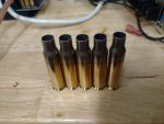
all the brass of the same brand/lots looks similar...its brand vs brand that are different, like lake city shows heavy marks, while hornady barely shows anything

ive only annealed a few types so far...but what i found was...

hornady 6creed brass (all same lot)...i weighed 10-15 pcs, had a pretty big spread, i think like 5-6 grains...i took 3 of the mid range pcs and it gave me codes like 134, 135, and 136...so i used the middle...i should have done a heavy piece and light piece, but i was loading up 20 rounds to go shoot, and didnt think about it at the time

lake city 308 (same lot)...same as above, but spread was smaller, like 2-3 grains iirc, i checked 3 pcs and got 155, 155, and 156...so i used 155

starline 223 (same lot)...did similar, spread was pretty small, i think it was all less than 2 grains...i checked 2 cases and got the same number, so i used that

above codes arent the actual number codes, just for examples...i cant remember them off the top of my head, theyre written down at home

id only expect the codes to be as consistent as the brass quality itself, but its still easier/more consistent than a flame and a roller imo...especially when changing out from magnums to 223 sized cases over time

i generally dont mix brass lots anyways, ive known that was bad practice for any consistency for a long time...the only thing i have mixed lot is some 308 Federal brass, but it is currently all loaded up with a generic 175 smk load i just use for random 308 stuff

i do have a bunch of lapua 223, 6.5creed, and 308...and some neck turned 6.5prc hornady, but all of that is loaded, as well, so i wont be able to mess with it until its shot up

all said, i dont think the amp is going to improve much of anything down range...i havent had any issues with how ive always loaded...it just makes it less hassle on my end for all the various stuff i reload...less fiddling, just push a button and go
 
Last edited:
  • Like
Reactions: spife7980
How are you satisfied with AMP? Can you post picture of case done with an AMP? I am looking into buying one too. Are you annealing after each firing?

Here’s some pics, left is hornady 6creed, right is lake city 308

0280B84A-5C54-4E5A-B4DB-3D17CAC84B3A.jpeg
 
  • Like
Reactions: igor79
progress so far,
i should have ordered stuff locally, not sure when i can expect stuff from china to arrive to go much further d'oh
thanks TSerrao, hope you dont mind that i have used your design principal for my project.


Hey, thanks OK buddy! We are here to help each other! ;)
I'm glad that was good for you! (y)
 
H
Hello, why did you opt for double layer coil? How did you calculate required inductance/ capacitance for that coil to achieve resonant freq. (assuming 120-125kHz )?

Can you post your electrical drawing, maybe we can see something what is pulling that idle current?

There is a very good explanation on https://www.rmcybernetics.com/science/diy-devices/diy-induction-heater
Hi buddy. I'm not doing myself the whole pcb. I'm using ZVS1000, like most of the other guys.
I did double coil to decrease the height of my coil, to improve magnetic field concentration. The KHz is being calculated by normal math, considering 6 x 0.33 uF caps and an inductor. So, I'm just matching the inductance with the LC circuit, in order to work around the KHz desired. In my case, I was expecting to work @ 105 KHz. Not that high as you are trying. I understood that if you increase too much the ressonance frequency (according to what the board was designed to work at) you loose performance. So, I'm trying to keep as close as possible of the 95KHz (the frequency that I saw that would be the manufacter default)
 
Looking forward to the result.
Bad news... the reason of almost reaching a perfect anealling was the power supply was providing less than 48V. Almost burnt.
But ok. I now bought another ZVS because I'm almost sure my problem is with that board.
It'll arrive till monday. So, as soon as I get it and test, I'll post my comments.
Hope now everything work properly! 🤦‍♂️
 
  • Like
Reactions: Bradv86
Over the last couple of days I put together an induction annealer setup. All components minus the coil were sourced from Amazon. I turned the coil myself from solid copper wire to ensure proper inductance and distance to the case. The power supply is 24V/15A. Switching frequency of the induction coil is ~120 kHz. The coil supplied with the ZVS unit was far too large in diameter and would not sufficiently heat the brass with the 24V/15A supply. Proper coil sizing is key. I have not found a need for any additional cooling. The PCB and components are barely getting warm.

The 1/8" rod under the coil is the release mechanism to allow the case to drop. I am contemplating adding a push/pull solenoid to automate the drop at the end of the cycle but at my processing rate it isn't necessary.

Using 750F Tempilaq as an indicator my run time for a .223 case is 3.4 seconds. A tenth of a second can make a significant difference. The picture showing both cases is only a delta of 0.2 seconds. A run time of just 7.5 seconds will have the brass glowing red hot as seen in the pic. That is far too hot for annealing but I provided the pic to illustrate that it doesn't take long to over anneal. Average power consumption during a cycle with the current setup is ~260W. With a different power supply and additional cooling the system can run to 1000W.

This is a sub $100 build and the results are consistent and repeatable.

Tim


Hi Tim,

Thank you very much for posting this. Do you have a wiring diagram? I just ordered the parts off amazon and I think I could figure it out, but I don't want to kill something that way.

Thanks,

Clint
 
The amp is cool. I'm still not sure if annealing does anything but I do it begrudgingly.
 

Attachments

  • 20200623_204652.jpg
    20200623_204652.jpg
    222.2 KB · Views: 156
update on mine... i am not sure the ammo can was a spectacular idea. It seems to hold in too much heat the way I had it setup. I fried my first board. Admittedly I was probably abusing it a bit, got like 150 in and realized that when I dropped the brass in on 151, it didnt sizzle when it hit water. Started to diagnose and noticed the first pic below.

Ordered a new board from Amazon that has a fan built onto it. The fan only worked when the bird was energized, so I took the wires and attached them to my power supply directly, so I could have the fan on constantly. Then I got an old fan off a stereo tower setup my DAD had 30 years ago... put that on the top of the ammo can for now. Heat is not as big of a problem.

But I noticed that I was basically heat treating the steel of the can around the copper coil leads. Cut apart some old MSD plug wires and tried to insulate a bit. Doesn't seem to have helped much. All in all, I'll likely move to something that isn't steel in the near future.

20200629_112654.jpg


20200629_112704.jpg


20200629_112710.jpg
 
But I noticed that I was basically heat treating the steel of the can around the copper coil leads. Cut apart some old MSD plug wires and tried to insulate a bit. Doesn't seem to have helped much. All in all, I'll likely move to something that isn't steel in the near future.

You may be inducing eddy currents in the can - and insulation won't change that. The can is pretty close to your coil, and the magnetic field coming off the coil could be losing power to the can. Do you have a current meter in-line, and can you tell how much current you're drawing with no case in the coil? Also, does your power supply do current limiting?
 
You may be inducing eddy currents in the can - and insulation won't change that. The can is pretty close to your coil, and the magnetic field coming off the coil could be losing power to the can. Do you have a current meter in-line, and can you tell how much current you're drawing with no case in the coil? Also, does your power supply do current limiting?

I'm sure that's it exactly. I noticed the time required to anneal is higher than normal after I put it in the box. Im going to put it back on a board soon. The box was cool, but not a fantastic idea.
 
I'm sure that's it exactly. I noticed the time required to anneal is higher than normal after I put it in the box. Im going to put it back on a board soon. The box was cool, but not a fantastic idea.

If you look at my build this is exactly the reason I cut the metal computer case side to a 1.5" outer frame and attached a wooden side panel to it. The metal around the coil pass through was getting hot from repeated annealing.
 
  • Like
Reactions: Ryridesmotox
I'm sure that's it exactly. I noticed the time required to anneal is higher than normal after I put it in the box. Im going to put it back on a board soon. The box was cool, but not a fantastic idea.

For what it's worth, I just built my case out of wood. But like Bradv86 mentions, wood or plastic around the general area instead of metal should alleviate most or all of that issue.

Edit to add - also, I added heat sinks to the bottom of my induction board, under the capacitors (looks like you blew one or more caps). Those are the big heat generator on the board, and adding some extra cooling the board beneath them seems to have helped keep it cool (plus a fan blowing directly down on them).
 
  • Like
Reactions: Ryridesmotox
I'm building a little frame out of MDF and plywood. Have a big fan in the back to blow a bunch of air through the apparatus.

The wiring is a bit steam punk... it sucks. But it works. And the top isn't fastened down yet. Going to do that tomorrow

I'm done with my big run of annealing, so this thing won't need to be struck up for a while. But i grabbed a few pieces and got the time set. 6.5 seconds with a 24v power supply and Jag brass. The brass seems pretty thick. MEN NATO brass takes a second less to get to thr same temps. Dunno why.

20200629_213034.jpg

20200629_213045.jpg

20200629_213056.jpg
 
Last edited:
  • Like
Reactions: jcal73 and davere
I took some more accurate measurements at 24.05 V and 28.20 V. The voltage and current measurements were taken at the ZVS board terminals. 4 V turned out to be pretty significant. i used the same lot of brass trimmed to the same length (1.750") for these tests. Until I receive my 900F and 1000F Tempilaq I consider the 750F Tempilaq change 4mm below the shoulder as my optimum baseline.

@24.05V

3.4 s (baseline) -> 11.40 A or 274 W

@28.20 V

2.8 s (new baseline) -> 12.75 A or 360W
3.0 s -> 13.00 A or 367 W
3.4 s -> 13.50 A or 381 W

As you can see a 4 V increase dropped the time from 3.4 s to 2.8 s. If I find I need a little more power with the additional Tempilaq temps I will move to the 36 V/15 A version of this supply. Current will rise as the brass heats up. My current figures here are peak measured during the cycle. If you are going to replicate this setup I would probably advise just going with a 36 V/ 20A supply right out of the gate.

Tim
How did you adjust the output voltage on the power supply?
 
How did you adjust the output voltage on the power supply?

Most of these have a potentiometer that is adjustable. Mine is near the output terminals. My 48v supply will run from about 39v to 55v if I remember right.
 
Thank you for letting me know. I think I’ll give this DIY project a try.
 
Hi guys.. I'm back!

Let me ask about something that is stil ldriving me crazy:
For the people who are already used to use the annealing process (no matter what machine is being used) and used Tempilaq750 and/or 800, how is the visual of the case "during" the annealing procedure? I mean, if you used Tempilaq 750 to asure the minimum temperature for your annealing and some other Tempilaq to makeyour adjustment no overheat the case, considering that your annealing is perfect with the best selected time, willthe case have the littlered glow or is it possible to achieve a good annealing with no glow at all?

Does anyone know something about this appearance of the case "during" the process?
Thanks
 
Does anyone know something about this appearance of the case "during" the process?

Depends on the caliber and brand of brass - and the lighting level in your room. I use Tempilaq 750 to determine a starting point, and then the pin gage process detailed earlier in the thread to dial in my anneal time. Absent some kind of AMP Aztec mode analysis, that seems to be the best way to get things just right that I've found, to date. With Hornady 6.5CM brass, I see a definite glow begin for a few tenths of a second before the cycle quits. With Lapua, it's just starting to begin to glow when the cycle ends - and that's with about a second longer cycle than the Hornady brass needs. That's with bright lighting in the room. If I turn the lights out, it's easier to see the glow - there's not much in either case, and neither gets up to a "white hot cherry red" kind of glow by any stretch.
 
  • Like
Reactions: TSerrao
Depends on the caliber and brand of brass - and the lighting level in your room. I use Tempilaq 750 to determine a starting point, and then the pin gage process detailed earlier in the thread to dial in my anneal time. Absent some kind of AMP Aztec mode analysis, that seems to be the best way to get things just right that I've found, to date. With Hornady 6.5CM brass, I see a definite glow begin for a few tenths of a second before the cycle quits. With Lapua, it's just starting to begin to glow when the cycle ends - and that's with about a second longer cycle than the Hornady brass needs. That's with bright lighting in the room. If I turn the lights out, it's easier to see the glow - there's not much in either case, and neither gets up to a "white hot cherry red" kind of glow by any stretch.
Thanks for your share!
I was asking this because some 30-30 brass got too soft, that the expander pull out a little the neck and deformedit. Even not gettingbright glow, it seems to me that was too much annealed.
 
Thanks for your share!
I was asking this because some 30-30 brass got too soft, that the expander pull out a little the neck and deformedit. Even not gettingbright glow, it seems to me that was too much annealed.

Sounds like that might be true - like it's probably way too soft, from the sound of it. It helps to keep the Tempilaq aligned on the case so you can actually watch it change during the process, too. You can always hit the "stop" button when things change, note that time and use it as your starting point, and then go about the verification process however you wish. The gage pin thing is pretty trick!
 
  • Like
Reactions: TSerrao
Th
Sounds like that might be true - like it's probably way too soft, from the sound of it. It helps to keep the Tempilaq aligned on the case so you can actually watch it change during the process, too. You can always hit the "stop" button when things change, note that time and use it as your starting point, and then go about the verification process however you wish. The gage pin thing is pretty trick!
Thanks for your advices! ;)
 
  • Like
Reactions: davere
I can't seem to find any info on this...

For purposes of isolating my ZVS board from heat, and also to facilitate pumbing my work coil to a water cooling setup, I would really like to use conventional wire to hook up my coil to the circuit board. However, I cannot find any info on whether this would be problematic or not. I realize it would need to be large gauge wire, and soldered to the coil. Could you give me any advice on this??

Thanks!

My board has connections for a standard wire in lieu of the little clamp/post method.
 
Mine too. I would like to run, say 12 gauge stranded wire from those connectors on the board, to a coil made from 1/8" copper tubing. The wire would be soldered to convenient spots on the tubing just far enough from the ends of the tubing to allow hose to be attached to the tubing for liquid cooling.

I don't know if this would interfere with the resonance, eddy currents, magnetic fields or not...

Vettepilot

Yes, you can solder wires onto the work coil to make your connection back to the ZVS board. I made mine like that when I first read Tim's excellent post, intending it to also be a temporary mechanical fix to support the coil while I tried things out. It worked so well I still have it like that many months later.


Insulated work coil.JPG
 
Eric,

Do you have any heat issues with the wire connecting the coil to the zvs board? I used 3 or 4 AWG to connect mine and the wire heats up quickly.

I am using the 48V/20A power supply and the 1000W ZVS board with 1/4" copper tubing in a double layer coil with about 1" ID.

I am considering trying a smaller gage wire (12 maybe, solid or stranded) or reconfiguring my setup to have the board connected directly to the coil as originally intented.


Since those pics, I have added a temp gauge to monitor the wire temp as well as the coolant temp.
 
Last edited:
Heat is not a problem with my setup, but then I only have a 36V supply, so it is quite likely that you have more amps flowing in your work coil and with heat being proportional to current squared, that could be significant.

Using stranded wire to connect the work coil instead of a single solid round conductor is a very good idea, it greatly reduces the unwanted "skin effect" at these frequencies (100 kHz ish). 12 AWG could be too small, my arrangement is equivalent to 4 strands each of about 13AWG.

Ideally we don't want to introduce any significant extra resistance (or inductance) to the circuit when we use additional wire to connect to the coil, so it is best to keep these connections as short as reasonably possible. Maybe you could move the circuit board closer to the coil ?

If that is not possible, where you run the connections back from the either side of the coil to the ZVS board, it is good practice to keep the wires close together. If not they will act like another large, single turn work coil, which makes your heating coil less effective and the stray magnetic field could also cause other electronic parts to miss behave.
 
Should I twist together the wires running from the circuit board to the work coil to help avoid the problems mentioned??
Thanks so much for the answers!
Vettepilot
 
I went ahead and tried some 10 AWG wire for connections, and as I suspected, the heat issue was slightly worse with a more rapid heat build up (although even though it reached a higher peak temp after a single firing of the ZVS, it probably would have cooled off quicker).

It is unfortunate that that particular ZVS board has its coil connections so far apart that it prevents an easier connection with either shortening and/or winding together as you suggest.

I guess I will move on to moving the board closer to the coil or connecting it directly to see if that helps.

Ultimately I would like to shorten the cycle times if I can, but with the bullet feeder I just built I can just set the rest interval before firing again long enough to control the temps indirectly by letting it idle until the wire temp drops sufficiently (still working on the feeders reliability since it will occasionally not drop a case from the hopper causing the sensor that detects a case in the roller to trigger the off signal to the timer).

Oh well...work in progress...
 
Can I use a solid state relay such as this to cycle my ZVS board on and off??

Edit: I better clarify... I need to be able to cycle/switch the power from my power supply to my ZVS board; not the power to my power supply. My power supply is home-made, and consists of a transformer, a diode bridge, and a very large capacitor. 48 volts dc at a possible 20 amps. Due to the large capacitor, it is not going to have a clean shut off mode. Hence the need to cycle/switch the power from the power supply to the ZVS board, not the AC power to the power supply.
 

Attachments

  • 1598665863062493412470.jpg
    1598665863062493412470.jpg
    10.5 KB · Views: 86
Last edited:
Can I use a solid state relay such as this to cycle my ZVS board on and off??

Edit: I better clarify... I need to be able to cycle/switch the power from my power supply to my ZVS board; not the power to my power supply. My power supply is home-made, and consists of a transformer, a diode bridge, and a very large capacitor. 48 volts dc at a possible 20 amps. Due to the large capacitor, it is not going to have a clean shut off mode. Hence the need to cycle/switch the power from the power supply to the ZVS board, not the AC power to the power supply.

I would be careful with that single pole relay...as I recall from the accurate shooter forum on this subject, a double pole relay would be better because it disconnects both positive and negative inputs to the ZVS and possible feed back when that much juice is cut off from the board (ie feed back on the negative line back into your power supply, etc...).

Try this amazon search link:

These types of relays have both a normally open and normally closed throughput controlled by the relay. They are not solid state, so they click when the relay closes, but I actually like that because I know the heater is firing. I have a cut out switch on the control circuit from the timer to the relay so that I can disable the ZVS board when testing other parts of the system, and I would be lying if I said I had never forgotten to reenable the ZVS after troubleshooting something.
 
Last edited:
Should I twist together the wires running from the circuit board to the work coil to help avoid the problems mentioned??
Thanks so much for the answers!
Vettepilot

To twist the wires together you would have to use longer pieces of wire, which will introduce slightly more unwanted resistance to the circuit. I would just run them close together and leave out the twist.
 
I went ahead and tried some 10 AWG wire for connections, and as I suspected, the heat issue was slightly worse with a more rapid heat build up

Even without considering the skin effect (where at high frequencies, current will only make good use of the outer part of the conductor), that single 10 AWG is giving you too much resistance. Connecting another wire of the same gauge in parallel will halve the heat dissipated. Add two more and you will be down to a quarter.
 
Can I use a solid state relay such as this to cycle my ZVS board on and off??

I believe others have used solid state relays like that successfully.

Mine uses an old fashioned relay that happened to be lying around. The sound of the relay releasing is my cue to manually feed another cartridge - it has me trained almost as well as Pavlov's dogs :)
 
How much would using a solid copper awg 4 instead of awg 8 influence the number of turns needed . There is of course more copper mass involved . Just asking because I have a supply of 4 already available . I have an o-scope and could probably build a circuit that could measure the actual inductance , but is that really necessary ?
 
so been google stalking this thread for a while. Mainly reloading 6.5cm and 300AAC.

I've got the first piece of the puzzle figured out for a steal: lightly used industrial meanwell 48V 21A power supply that can be paralleed if needed. can snag up to 4 of them for $79 a piece (Currently $260 of mouser).

The 1000W ZVS board seems easy to come by. Any harm in grabbing the 1800w board and only running at 1000w ? seem like a not terribly expensive way to add some thermal mass dampening to the components heating up (plan to run at least 12V fans in a knock off pelican box).

I don't think I plan to need a case feeder and duty cycle relatively low. Should I plan to build a solid copper coil or go straight to water cooled coil?

First off that is a great deal on the supply and it will likely do everything you need with just one... Maybe short of a .50BMG.

I imagine your coil design will be different using that 1800w board in regard to turn and diameter. For 6.5CM and BLK you won't really need anywhere near that power. I don't see a reason you can't, but your coil may not fall into the same number of turns and doesn't that done of us here have used. You'll be figuring it out solo.

I am hand feeding and I'm happy to have mine water cooled. It got hot fast before the cooling loop was active with a 600w supply on the 1kw board.

Brad: Thanks for the quick reply. I will probably pick up 2 power supplies and a 1kw board to start.
 
Ok, got mine water cooled now. I also went to a 36v supply, 36v induction module, 1/8 tube, water wetter. I was hoping to see a decrease in anneal time. But I don't see much of a decrease, half second or so for PMC 308. It takes 7.5 seconds, which seems to be a bit longer than most of you other guys. Also when I hit the button to start annealing, it drops to 22-23v output. Seems like I set something up incorrectly. Or is that normal? I'd lean more on me fucking something up, as I'm not super electrician or anything.

Anyway, here is the setup. I am thinking about redoing the box it sits in, but not until I get this thing figured out.

20200915_110812.jpg

20200915_110806.jpg

20200915_110727.jpg

Factory PMC (bottom) vs my annealed PMC
20200915_111458.jpg
 
  • Like
Reactions: jcal73
e water cooled now. I also went to a 36v supply, 36v induction module, 1/8 tube, water wetter. I was hoping to see a decrease in anneal time. But I don't see much of a decrease, half second or so for PMC 308. It takes 7.5 seconds, which seems to be a bit longer than most of you other guys. Also when I hit the button to start annealing, it dr

How high is the case in the coil? How much current can the power supply produce?
 
How high is the case in the coil? How much current can the power supply produce?

The case body is half way in the coil. The supply is an advertised 36v 10A 360W. Im less concerned about the time it takes to anneal and more concerned that I didn't connect everything properly. Though, everything seems to be working appropriately. I did a handful of cases all in a row and they all came out pretty much the same.

20200915_132444.jpg

20200915_122731.jpg
 
Last edited:
  • Like
Reactions: jcal73
So I just realized I ordered a board that can handle 20A 1000W. So I'm going to return my power supply and get a beefier one. I imagine that greater wattage and amps will decrease my anneal time and increase heat... or whatever.
 
So I just realized I ordered a board that can handle 20A 1000W. So I'm going to return my power supply and get a beefier one. I imagine that greater wattage and amps will decrease my anneal time and increase heat... or whatever.

Yep I believe you have a power issue. My power supply is 48v and is variable +/- some amount. I have found that I can run it all the way down to 39V and most cases are happy there.

My results when running 39V are that with a similar sized coil I can trip my power supply if I have too much case inserted, which shuts off over 12.5A. I'm guessing that at 36V you are drawing at or over 10A and the voltage is dipping before the unit shuts down.

FGMM .308 from when I first started playing with it for reference. Probably overdid it but you can achieve the "look" that everyone likes with a touch less time haha. Don't have my log book handy but this is on the 1000w 20A 48V board. I think most of these 1kw boards are nearly identical.
 

Attachments

  • 308brass.jpg
    308brass.jpg
    202.1 KB · Views: 112
My board is only rated to 36v. I didn't notice that when I ordered or I would have gone with a 48v board.

So I'm thinking about staying with a 24v supply since the 36v supplies seem to be limited to either a 360w, 500w, or a 1kw unit. The 1kw is 27a so I think thats going to be a problem? I honestly don't know what I need to watch for. I have a .6 inch ID coil of 1/8, 9 wraps.

So with a 36v 20a 1kw board, I'm thinking I'll go with a 36v 13.8a 500w supply. Its 140w more than my current supply at +3.8a. Or a 24v supply 20a at 500w. Not sure though. Anyone have any insight?
 
So I just realized I ordered a board that can handle 20A 1000W. So I'm going to return my power supply and get a beefier one. I imagine that greater wattage and amps will decrease my anneal time and increase heat... or whatever.

Its hard to tell from the pics you show, but something else that jumped out at me as a possibility is the timer unit you are using...it looks like it is switching the full output of the power supply into the ZVS board. I don't know what the specs are on the timer, but it may be limiting the throughput to the ZVS is some way and if you upgrade to a larger supply the problem may increase. Using the timer to trigger a beefier relay with a 12 volt circuit may help if that is the case (I assume some of your circuits, fan pump etc., are 12 volt...)

A basic circuit diagram (hand drawn or in Paint) would help diagnosing problem (include specs for each component you used). (here is an example from my build - https://drive.google.com/open?id=16gGj4jPtPGdh--QO44VOZwWJYbIx4TM6)