I buzzed right by that the board is 36v max. My bad.
The supply is going to output whatever the draw of the system is. It won't autmatically just output 27A and fry the board. You will have some amount of idle current (no brass in the coil) and the load will increase based on the size, material, and location of whatever is put inside of the coil. If you have an ammeter inline in your setup you can probably mitigate issues by inserting brass less and creeping up to more depth and stopping shy of 20A. I don't know how much heat this will generate when approaching the limits of the board, but it should be possible.
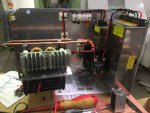
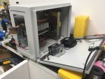
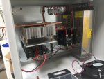
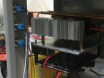
My setup is done how hdmunger described, with a 100A relay between my supply and ZVS board. It is controlled by a timed relay on a completely separate 12v supply. It doesn't have to be done this way as you have seen several versions working with other control types.
The supply is going to output whatever the draw of the system is. It won't autmatically just output 27A and fry the board. You will have some amount of idle current (no brass in the coil) and the load will increase based on the size, material, and location of whatever is put inside of the coil. If you have an ammeter inline in your setup you can probably mitigate issues by inserting brass less and creeping up to more depth and stopping shy of 20A. I don't know how much heat this will generate when approaching the limits of the board, but it should be possible.
My setup is done how hdmunger described, with a 100A relay between my supply and ZVS board. It is controlled by a timed relay on a completely separate 12v supply. It doesn't have to be done this way as you have seen several versions working with other control types.